Lowrance NAC-3 Autopilot Computer Network Pilot Installation Manual ACP - Page 65
Proportional Solenoid Connection
 |
View all Lowrance NAC-3 Autopilot Computer manuals
Add to My Manuals
Save this manual to your list of manuals |
Page 65 highlights
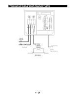
PROPORTIONAL SOLENOID CONNECTION These are general wiring instructions only, showing the installation of the ACP 2 Computer Unit outputs to drive proportional solenoid valves. The continuous drive pump motor will also require a heavy duty supply, this is not shown on this diagram. The clutch output could be used to control the motor supply, the clutch output is only active while the rudder is being moved. (See Setting The Rudder Drive Type in Section 5). COMPASS DRIVE SUPPLY IN DRIVE SUPPLY OUT ++ Blk R Blk R CLU ALM TS1 Bl TS2 TS3 Br Blk G Bl Br Blk Bl Bl Y Y R Blk HAND HELD G G V V Br Br W W R R Bl R NET G W G R R Blk Bl RRU MOB BOAT SPEED TS4 O/G O/G Y G W Bl R Bl R G JOYSTICK Heavy Duty Power Supply Black Circuit Breaker Red Brown Blue Clutch output if required Red Black Valve Interface Solenoid Valves Port Rudder Reference Unit Starboard 4 - 17
-
 1
1 -
2
-
3
-
4
-
5
-
6
-
7
-
8
-
9
-
10
-
11
-
12
-
13
-
14
-
15
-
16
-
17
-
18
-
19
-
20
-
21
-
22
-
23
-
24
-
25
-
26
-
27
-
28
-
29
-
30
-
31
-
32
-
33
-
34
-
35
-
36
-
37
-
38
-
39
-
40
-
41
-
42
-
43
-
44
-
45
-
46
-
47
-
48
-
49
-
50
-
51
-
52
-
53
-
54
-
55
-
56
-
57
-
58
-
59
-
 60
60 -
 61
61 -
 62
62 -
 63
63 -
 64
64 -
 65
65 -
 66
66 -
 67
67 -
 68
68 -
 69
69 -
 70
70 -
71
-
72
-
73
-
74
-
75
-
76
-
77
-
78
-
79
-
80
-
81
-
82
-
83
-
84
-
85
-
86
-
87
-
88
-
89
-
90
-
91
-
92
-
93
-
94
-
95
-
96
-
97
-
98
-
99
-
100
-
101
-
102
-
103
-
104
-
105
-
106
-
107
-
108
-
109
 |
 |
