LiftMaster SL3000501U CSW200501U Setup and Operation Manual - Page 11
Expansion Board, Expansion Board Reference, Exit Fail Switch, Quick Close Switch
 |
View all LiftMaster SL3000501U manuals
Add to My Manuals
Save this manual to your list of manuals |
Page 11 highlights
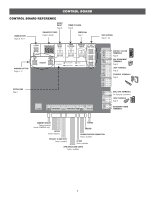
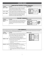
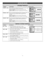
EXPANSION BOARD To AVOID damaging the circuit board, relays or accessories, DO NOT connect more than 42 Vdc (32 Vac) to the AUX relay contact terminal blocks. EXPANSION BOARD REFERENCE PLUG-IN LOOP DETECTOR INPUTS For Plug-In Loop Detectors (Model LOOPDETLM) SHADOW INTERUPT EXIT OPEN CLOSE POWER 1 EYE ONLY 2 EYE/ EDGE 3 EYE/ EDGE COM SBC OPN CLS STP COM TO MAIN BOARD MAIN CONTROL BOARD CONNECTION Connected at the factory. EYES/EDGE TERMINALS Page 12 CONTROL STATION TERMINALS Page 12 LOOP INPUTS Page 13 QUICK CLOSE SWITCH See below. ANTI TAIL SWITCH See below. RELAY 2 WITH CORRESPONDING SWITCHES Page 11 EXIT FAIL SWITCH See below. AC FAIL SWITCH Not used. RELAY 1 WITH CORRESPONDING SWITCHES Page 11 OPEN CLOSE EXIT FAIL SWITCH If the EXIT plug-in loop detector (model LOOPDETLM) detects a fault, then the gate will open and remain open until fault is cleared. If the EXIT plug-in loop detector (model LOOPDETLM) detects a fault, faults are ignored (EXIT loop is faulted and inoperative). NOT USED AC FAIL SWITCH ANTI TAIL SWITCH OFF When CLOSE EYES/Interrupt loop is activated it causes a closing gate to stop and reverse. ON When CLOSE EYES/Interrupt loop is activated it causes a closing gate to pause. Once the vehicle is clear the gate will continue to close. QUICK CLOSE SWITCH ON No change to the gate's normal operation. OFF When CLOSE EYES/Interrupt loop is deactivated it causes an opening or a stopped gate to close (ignores the Timer-to-Close). 10
-
 1
1 -
2
-
3
-
4
-
5
-
 6
6 -
 7
7 -
 8
8 -
 9
9 -
 10
10 -
 11
11 -
 12
12 -
 13
13 -
 14
14 -
 15
15 -
 16
16 -
17
-
18
-
19
-
20
-
21
-
22
-
23
-
24
-
25
-
26
-
27
-
28
-
29
-
30
-
31
-
32
-
33
-
34
-
35
-
36
-
37
-
38
-
39
-
40
-
41
-
42
-
43
-
44
-
45
-
46
-
47
-
48
-
49
-
50
-
51
-
52
-
53
-
54
-
55
-
56
-
57
-
58
-
59
-
60
 |
 |
