LiftMaster RSW12U RSW12U Compact Installation Manual - Page 4
Step 3
 |
View all LiftMaster RSW12U manuals
Add to My Manuals
Save this manual to your list of manuals |
Page 4 highlights
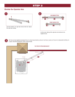
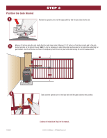
Position the Gate Bracket 1 STEP 3 Position the operator arm onto the output shaft so that the pin slides into the slot. Slot Pin Output shaft 2 Measure 33 inches along the gate length from the gate hinge center. Measure 27-1/2 inches up from the concrete pad to the gate bracket position on the gate as shown. NOTE: It may be necessary to attach horizontal reinforcement to the gate before attaching the gate bracket. Use the set screws on the arm to temporarily hold the arm in place while determining the correct measurements. 33" 27-1/2" 3 Make sure the operator arm is level and tack weld the gate bracket in this position. PAS001 Continue to Installation Step 5 in the manual. © 2015, LiftMaster - All Rights Reserved
-
 1
1 -
 2
2 -
 3
3 -
 4
4 -
 5
5 -
 6
6 -
 7
7 -
 8
8 -
 9
9 -
 10
10 -
11
-
12
 |
 |

Position the Gate Bracket
STEP 3
1
2
3
PAS001
© 2015, LiftMaster – All Rights Reserved
Position the operator arm onto the output shaft so that the pin slides into the slot.
Measure 33 inches along the gate length from the gate hinge center. Measure 27-1/2 inches up from the concrete pad to the gate
bracket position on the gate as shown.
NOTE:
It may be necessary to attach horizontal reinforcement to the gate before attaching the
gate bracket. Use the set screws on the arm to temporarily hold the arm in place while determining the correct measurements.
Make sure the operator arm is level and tack weld the gate bracket in this position.
Continue to Installation Step 5 in the manual.
Slot
Pin
Output shaft
33"
27-1/2"