LiftMaster RSW12U RSW12U Compact Installation Manual
LiftMaster RSW12U Manual
 |
View all LiftMaster RSW12U manuals
Add to My Manuals
Save this manual to your list of manuals |
LiftMaster RSW12U manual content summary:
- LiftMaster RSW12U | RSW12U Compact Installation Manual - Page 1
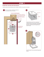
SWING GATE OPERATORS MODELS CSW24U, RSW12U, AND CSW200U • THIS PRODUCT IS TO BE INSTALLED AND SERVICED BY A TRAINED GATE SYSTEMS TECHNICIAN ONLY. • These instructions are for applications where the gate operator arm may hit an obstruction during movement. If the distance between the open gate and - LiftMaster RSW12U | RSW12U Compact Installation Manual - Page 2
instructed. 1 Refer to the illustration to determine the location for 2 the concrete pad, conduit, and operator. TOP VIEW OF OPERATOR AND GATE is required. Center of gate hinge 6" Above Ground Below the frost line. (Gate Open 90°) 26-1/2" from the center of the gate hinge to the center of - LiftMaster RSW12U | RSW12U Compact Installation Manual - Page 3
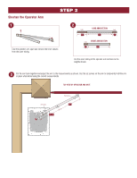
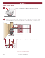
shown. Use the set screws on the arm to temporarily hold the arm in place while determining the correct measurements. TOP VIEW OF OPERATOR AND GATE Set screw 25-1/2" Set screw 23" - LiftMaster RSW12U | RSW12U Compact Installation Manual - Page 4
to temporarily hold the arm in place while determining the correct measurements. 33" 27-1/2" 3 Make sure the operator arm is level and tack weld the gate bracket in this position. PAS001 Continue to Installation Step 5 in the manual. © 2015, LiftMaster - All Rights Reserved - LiftMaster RSW12U | RSW12U Compact Installation Manual - Page 5
RSW12U, ET CSW200U • CE PRODUIT DOIT ÊTRE EXCLUSIVEMENT INSTALLÉ ET ENTRETENU PAR UN PERSONNEL DÛMENT FORMÉ SUR LES SYSTÈMES DE PORTAIL. • Ces instructions ées dans ces instructions sont génériques. Votre actionneur peut avoir une apparence différente. LiftMaster 845 Larch Avenue Elmhurst, IL 60126- - LiftMaster RSW12U | RSW12U Compact Installation Manual - Page 6
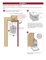
ÉTAPE 1 Installer la dalle de béton et l'actionneur Vérifier les codes de construction nationaux et locaux avant l'installation. NE PAS faire fonctionner l'actionneur avant que cela soit expressément indiqué. 1 Consulter l'illustration pour déterminer l'emplacement de la 2 plaque de béton, de la - LiftMaster RSW12U | RSW12U Compact Installation Manual - Page 7
ÉTAPE 2 Raccourcissez le bras de l'actionneur 1 Démontez le bras de l'actionneur et retirez les gaines internes à l'intérieur des tubes. 2 (coupez) PARTIE LONGUE DU BRAS (coupez) 10 po. 22 po. 4 po. (coupez) PARTIE COURTE DU BRAS 20 po. 4 po. Coupez les tubes externes du bras de l' - LiftMaster RSW12U | RSW12U Compact Installation Manual - Page 8
Positionnez le support de la barri ajouter un renfort horizontal supplémentaire à la barrière avant d'attacher le support de la barrière. Utilisez les vis de serrage pour maintenir le de l'actionneur est droit et clouez le support de la barrière dans cette position. PAS001 Continuer à l'étape 5 - LiftMaster RSW12U | RSW12U Compact Installation Manual - Page 9
PORTÓN GIRATORIO PARA VEHÍCULOS MODELOS CSW24U, RSW12U, Y CSW200U • ESTE PRODUCTO DEBE SER cm) deberá realizarse una instalación compacta. • Consultar el manual de instalación para ver las advertencias, instrucciones, prueba y programaci diferente. LiftMaster 845 Larch Avenue Elmhurst, IL 60126-1196 - LiftMaster RSW12U | RSW12U Compact Installation Manual - Page 10
PASO 1 Construir la plataforma de concreto e instalar el operador Verifique los códigos nacionales y locales antes de la instalación. NO active el operador hasta que se le indique. 1 Consultar la ilustración para determinar la ubicación 2 de la base de concreto, el conducto y el operador. VISTA - LiftMaster RSW12U | RSW12U Compact Installation Manual - Page 11
Acortar el brazo del operador PASO 2 1 Desarmar el brazo y quitar los manguitos internos de los tubos. 2 (cortar) SECCIÓN LARGA DEL BRAZO (cortar) 10 pulg. 22 pulg. 4 pulg. (cortar) SECCIÓN CORTA DEL BRAZO 20 pulg. 4 pulg. Cortar el tubo externo del brazo a la medida indicada. 3 Volver a - LiftMaster RSW12U | RSW12U Compact Installation Manual - Page 12
-1/2 pulg. 3 Verificar que el brazo esté nivelado y fijar la ménsula en esta posición con puntos de soldadura. PAS001 Continuar con el paso 5 de instalación del manual. © 2015, LiftMaster - Reservados todos los derechos de ley
-
 1
1 -
 2
2 -
 3
3 -
 4
4 -
 5
5 -
 6
6 -
 7
7 -
8
-
9
-
10
-
11
-
12
 |
 |
•
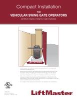
THIS PRODUCT IS TO BE INSTALLED AND SERVICED BY A TRAINED GATE
SYSTEMS TECHNICIAN ONLY.
•
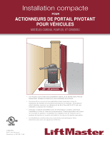
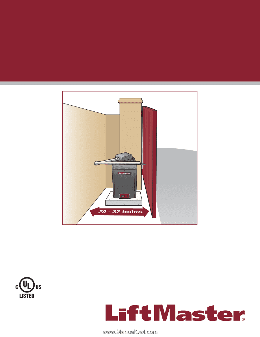
These instructions are for applications where the gate operator arm may hit an
obstruction during movement. If the distance between the open gate and an
obstruction is between 20 to 32 inches, a compact installation is necessary.
•
Refer to the installation manual for complete information regarding warnings,
installation, testing, and programming. Each application is unique and it is the
responsibility of the purchaser, installer and end user to ensure that the total gate
system is installed and operated properly.
•
The images in these instructions are generic. Your operator may look different.
LiftMaster
845 Larch Avenue
Elmhurst, IL 60126-1196
Compact Installation
FOR
VEHICULAR SWING GATE OPERATORS
MODELS CSW24U, RSW12U, AND CSW200U