LiftMaster HDSL24UL LiftMaster HDSL24UL HDSW24UL Wiring Diagram - English Fren
LiftMaster HDSL24UL Manual
 |
View all LiftMaster HDSL24UL manuals
Add to My Manuals
Save this manual to your list of manuals |
LiftMaster HDSL24UL manual content summary:
- LiftMaster HDSL24UL | LiftMaster HDSL24UL HDSW24UL Wiring Diagram - English Fren - Page 1
installed with this operator at each entrapment zone. Use ONLY LiftMaster approved entrapment protection devices (refer to the accessory page of manual). • See manual prior to servicing system Non-monitored contact closure devices are not supported. Make sure connected devices are monitored. Check - LiftMaster HDSL24UL | LiftMaster HDSL24UL HDSW24UL Wiring Diagram - English Fren - Page 2
de détection doivent être installés avec cet actionneur à chaque zone de piégeage. Utiliser UNIQUEMENT les dispositifs de protection contre le piégeage LiftMaster approuvés (consulter la page des accessoires). • Avant les travaux, consulter le manuel pour les instructions d'entretien et d'essai de
-
 1
1 -
 2
2
 |
 |

CONTROL
PWR IN
PWR OUT
DC
PWR
BAT
DC PWR FUSES
30A 32V
DC PWR FUSES
30A 32V
ACCESSORY ON POWER
24 VDC 1 A Maximum
N.C.
POWER SW
24 VDC 1 A Maximum
Jumper
PRODUCT
ID
ALARM
MECHANICAL
INTERLOCK
(For slide version only)
POWER
ADAPTER
BOARD
Control function of photoelectric
sensor or edge sensor for the
OPEN or CLOSE cycle.
PLUG-IN
LOOP
DETECTOR
Model
LOOPDETLM
EXPANSION BOARD
N.C.
JUMPER
THREE
BUTTON
STATION
SINGLE BUTTON
CONTROL STATION
PHOTOELECTRIC SENSORS
PHOTOELECTRIC SENSORS
or
EDGE SENSORS
LOCKS
ACCESSORY
POWER
DUAL
GATES
ENTRAPMENT
PROTECTION
LOOPS
CONTROLS
EDGE SENSOR
for CLOSE cycle
SHADOW LOOP
EXIT LOOP
PHOTOELECTRIC SENSORS or EDGE SENSOR
for OPEN cycle
Shielded Twisted Pair Cable
(Primary/Secondary link to other gate operator) Ground the
shield of the cable to the chassis ground of each operator.
CONTROL BOARD
ANTENNA
RESET SWITCH
MOTOR
DRIVE
APS ENCODER
BLDC MOTOR
BATTERY SWITCH
TRANSFORMER
BRIDGE RECTIFIER
EMI BOARD
12V SOLAR PANELS
IN SERIES
INPUT POWER
CONNECTION
12V BATTERIES
IN SERIES
RELAY ADAPTER
BOARD
SHADOW
LOOP
INTERRUPT
LOOP
Control
function of
Auxiliary
Relays
Red
Black
OPEN and COM:
Hard Open (line-of-sight)
CLOSE and COM:
Hard Close (line-of-sight)
STOP and COM:
Hard Stop(line-of-sight)
EXIT:
Soft Open (used for exit probe, telephone entry, external exit
loop detector, or any device that would command the gate to open)
PHOTOELECTRIC SENSORS
for CLOSE cycle
HEATER KIT
AC POWER
SWITCH
POWER BOARD
POWER BOARD
EXIT
LOOP
LiftMaster.com
© 2019, LiftMaster
All Rights Reserved
01-39240-13C
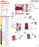
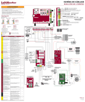
WIRING DIAGRAM
Models HDSL24UL and HDSW24UL
Press and hold
STOP...
...then press and
hold CLOSE...
...then press and hold OPEN
until "Er" shows.
CODE SEQUENCE NUMBER
The first number shown is the most
recent code (example: “01”). The
display will show the sequence of
codes that occurred starting with “01”
and going up to code “20”.
CODE NUMBER
The second number shown after the
code sequence number is the code itself
(31-99, example” “31”).
A SECOND LATER
....
The operator will show the code sequence number followed by the code number:
Diagnostic Codes
TO VIEW THE CODES:
LiftMaster System
Installed System
Informational
External Entrapment Protection
Inherent Entrapment Protection
To reduce the risk of INJURY or DEATH:
•
Turn both the AC Power and Battery switches to OFF position BEFORE installing or
servicing operator.
•
Replace ONLY with fuse of same type and rating.
•
To be compliant with UL325 and industry safety guidelines, qualified monitored external
entrapment protection devices such as photoelectric sensors or edge sensors are required
to be installed with this operator at each entrapment zone. Use ONLY LiftMaster approved
entrapment protection devices (refer to the accessory page of manual).
•
See manual prior to servicing regarding maintenance and required safety testing.
CODE COLOR KEY:
CODE
MEANING
SOLUTION
SAVED
31
Control board has experienced an internal
failure.
Disconnect all power, wait 15 seconds,
then reconnect power (reboot). If issue
continues, replace main control board.
NO
34
Absolute Position Encoder error, not getting
position information from encoder
Check APE assembly and wiring
connections. Replace the APE assembly if
necessary.
YES
35
Max-run-time exceeded error
Check for an obstruction, then reprogram
the limits.
YES
36
Product ID error
Was the control board just replaced? If
so, erase limits, enter limit setup mode
and set limits. If not, disconnect all power,
wait 15 seconds, then reconnect power
before changing product ID harness.
YES
37
Product ID failure
Unplug product ID harness then plug back
in. Disconnect all power, wait 15 seconds,
then reconnect power before replacing
product ID harness.
YES
38
Hard stop limit (Arm 1)
Limit may be set too tightly against a non-
resilient hard stop (re-adjust limit).
Operator may be at end of travel
(re-adjust mounting).
NO
40
Battery overvoltage
Too much voltage on the battery. Check
harness. Make sure there is NOT a 24V
battery on a 12V system.
YES
41
Battery overcurrent
Possible short of the battery charge
harness. Check harness. Make sure you
do NOT have a 12V battery on a 24V
system.
YES
42
No battery at boot up
Check battery connections and
installation. Replace batteries if depleted
to less than 20V on a 24V system or less
than 10V on a 12V system. Make sure
there is NOT a single 12V battery on a
24V system.
YES
43
Exit loop error
Failure or missing loop (SHORT or OPEN -
LiftMaster Plug-in Loop Detector only).
Check loop wiring throughout connection.
May be a short in the loop, or an open
connection in the loop.
YES
44
Shadow loop error
45
Interrupt loop error
46
Wireless edge battery low
Replace batteries in wireless edge.
YES
47
Motor Drive Fault
Check motor drive connections.
Disconnect all power, wait 15 seconds,
then reconnect power (reboot). If issue
persists, replace motor.
YES
48
Hall Sensor Fault
Check motor and motor drive
connections. Disconnect all power, wait
15 seconds, then reconnect power
(reboot). If issue persists, replace motor.
YES
50*
Gate overspeed detected
*Note: Code 50 only applies to Slide gate
operators.
Make sure the gate is installed on a level
surface and not on an excessive grade.
YES
53
Brownout occurred
AC/DC board supply dipped below
allowable level. Review power supply and
wiring. If rebooting, ensure enough time
for discharge of power to force a fresh
boot.
YES
54
Wireless second operator communication
error
Check the second operator for power. If
OFF, restore power and try to run the
system. If powered, deactivate the
wireless feature and then re-learn the
second operator.
YES
60
Minimum number of monitored entrapment
protection devices not installed.
Review monitored entrapment protection
device connections. Slide gate operators
require a minimum of two external safety
devices; one in the close and one in the
open direction.
NO
61
CLOSE EYE/INTERRUPT held more than 3
minutes
Check wired input on main control board;
check for alignment or obstruction.
YES
62
CLOSE EDGE held more than 3 minutes
63
OPEN EYE/EDGE held more than 3 minutes
64
CLOSE EYE/INTERRUPT held more than 3
minutes
Check wired input on expansion board;
check for alignment or obstruction.
YES
65
CLOSE EYE/EDGE held more than 3 minutes
66
OPEN EYE/EDGE held more than 3 minutes
67
Wireless edge triggered more than 3
minutes
Check wired input for wiring issue or
obstruction.
YES
68
Wireless edge loss of monitoring
Check wireless edge inputs.
YES
69
Wireless edge triggered
IF an obstruction occurred, no action
required. If an obstruction did NOT occur,
check inputs and wiring.
NO
70
CLOSE EYE/INTERRUPT triggered, causing
reversal, preventing close, or resetting TTC
IF an obstruction occurred, no action
required. If an obstruction did NOT occur,
check alignment, inputs, and wiring on
main control board
NO
71
CLOSE EDGE triggered, causing reversal, NO
preventing close, or canceling TTC
72
OPEN EYE/EDGE triggered, causing reversal
or preventing opening
73
CLOSE EYE/INTERRUPT triggered, causing
reversal, preventing close, or resetting TTC
IF an obstruction occurred, no action
required. If an obstruction did NOT occur,
check alignment, inputs, and wiring on
expansion board.
NO
74
CLOSE EYE/EDGE triggered, causing reversal
and preventing close or canceling TTC
75
OPEN EYE/EDGE triggered, causing reversal
or preventing opening
80
Close input (EYE/EDGE) communication fault
from other operator
Check inputs and communication method
between operators, either wired bus or
radio. Ensure operator is powered. May
have to erase the wireless communication
and reprogram the two operators.
YES
81
Open input (EYE/EDGE) communication fault
from other operator
82
Close input (EYE/EDGE) communication fault
(expansion board)
Check the connections between the main
board and the expansion board.
YES
83
Open input (EYE/EDGE) communication fault
(expansion board)
84
Non-monitored device detected on the
wireless safety system
Non-monitored contact closure devices
are not supported. Make sure connected
devices are monitored. Check edges for
proper orientation and resistive end cap
connection.
YES
91
Force reversal (Operator 1)
Check for obstruction. If no obstruction,
check that the mechanical assembly is
engaged and free to move. See Limit,
Speed and Force Adjustment page 23.
YES
93
RPM / STALL reversal (Operator 1)
Check for obstruction. If no obstruction,
check the operator wiring and that the
mechanical assembly is engaged and free
to move. Replace APE assembly.
YES
95
Motor start failure
Operator attempted to run, no response
from motor drive assembly. Check
connector and harness. If connected
properly and still not working, replace
motor and/or motor drive.
YES
96
Power Board Fault
Check connections to power board. Power
cycle and retry. Replace power board if
issue persists.
YES
99
Normal operation
No action required
YES