LiftMaster CSW24V CSW24V Manual
LiftMaster CSW24V Manual
 |
View all LiftMaster CSW24V manuals
Add to My Manuals
Save this manual to your list of manuals |
LiftMaster CSW24V manual content summary:
- LiftMaster CSW24V | CSW24V Manual - Page 1
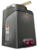
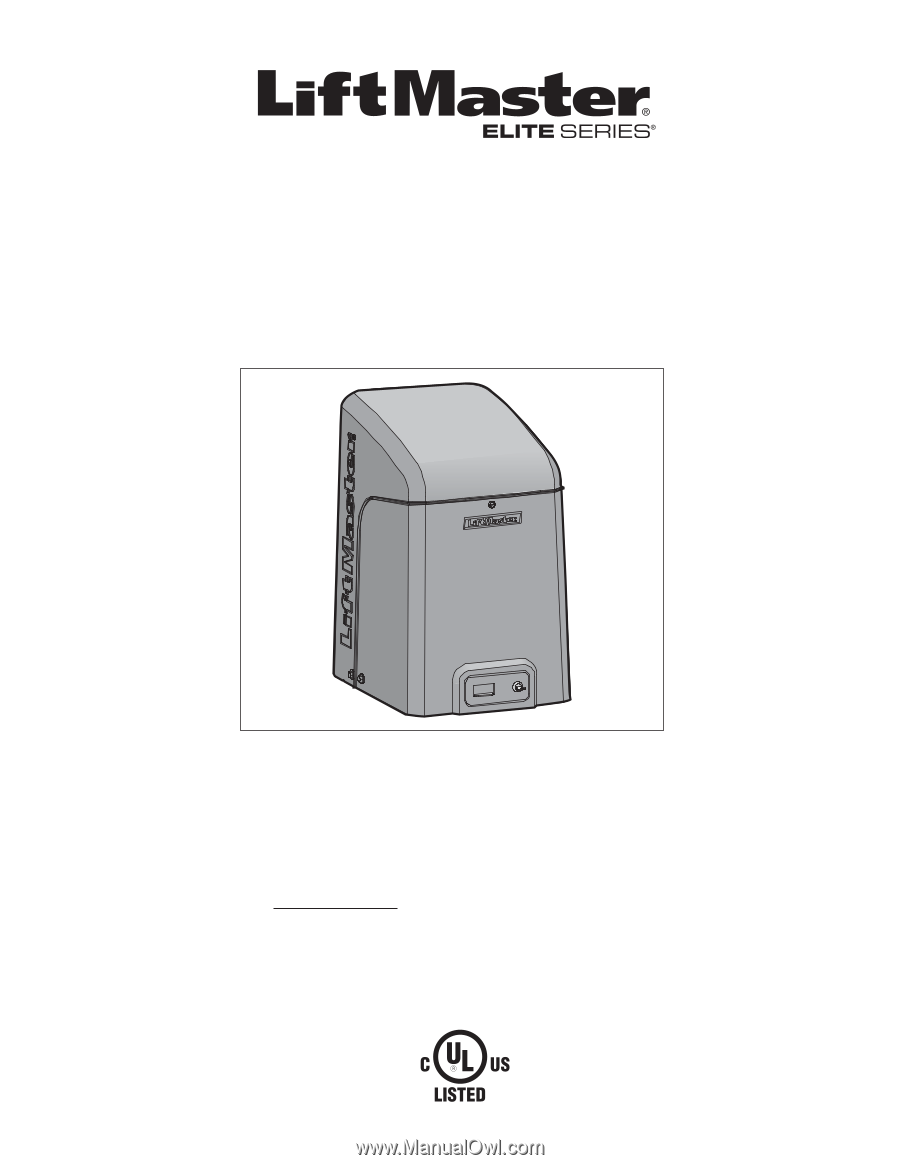
CSL24V™ & CSL24VH™ VEHICULAR SLIDE GATE OPERATOR INSTALLATION MANUAL Your model may look different than the model illustrated in this manual. THIS PRODUCT IS TO BE INSTALLED AND SERVICED BY A TRAINED GATE SYSTEMS TECHNICIAN ONLY. Visit www.liftmaster.com to locate a professional installing dealer - LiftMaster CSW24V | CSW24V Manual - Page 2
- LiftMaster CSW24V | CSW24V Manual - Page 3
attempting to install, operate or maintain the operator, you must read and fully understand this manual and follow all safety instructions. • DO NOT attempt repair or service of your gate operator unless you are an Authorized Service Technician. 1 SAFETY SYMBOL AND SIGNAL WORD REVIEW MECHANICAL - LiftMaster CSW24V | CSW24V Manual - Page 4
sensors such as photoelectric sensors, • Type B2 - Contact sensors such as gate edges NOTE: UL requires that all installations must have warning signs placed in plain view on both sides of the gate to warn pedestrians of the dangers of motorized gate systems. 2 UL325 MODEL CLASSIFICATIONS II IV - LiftMaster CSW24V | CSW24V Manual - Page 5
Swinging gates shall not open into public access areas. 7. The gate must be properly installed and work freely in both directions prior to the installation of the gate operator. 3 8. Controls intended for user activation must be located at least 6 feet (1.8 m) away from any moving part of the gate - LiftMaster CSW24V | CSW24V Manual - Page 6
at horizontal swing gates: that time. 4.1.1 Gates shall be designed, constructed and installed so as not to create an entrapment area between the gate and the supporting structure or other 3. VEHICULAR HORIZONTAL SLIDE GATES fixed object when the gate moves toward the fully open position - LiftMaster CSW24V | CSW24V Manual - Page 7
is not working or loses power or the beam is blocked, then ALL gate operation in that direction will stop. Unmonitored photoelectric sensor models AOMRON and RETROAB are also acceptable. Sensor for Open Cycle Safety Non-Contact Sensor Sensor for Close Cycle ! ProIpnesridtye PrOopuetsritdye - LiftMaster CSW24V | CSW24V Manual - Page 8
access through openings anywhere the gate may travel. • Mount controls at least 6 feet (1.8 m) from the gate or ANY moving part of the gate. • Install Warning signs on EACH side of gate in PLAIN VIEW. Permanently secure each Warning sign in a suitable manner using fastening holes. • This operator is - LiftMaster CSW24V | CSW24V Manual - Page 9
. • SAVE THESE INSTRUCTIONS. • ALWAYS wear protective gloves and eye protection when changing the battery or working around the battery compartment. TROUBLESHOOTING To protect against fire and electrocution: • DISCONNECT power (AC or solar and battery) BEFORE installing or servicing operator. For - LiftMaster CSW24V | CSW24V Manual - Page 10
+ CARTON INVENTORY & OPERATOR DIMENSIONS OPERATOR SPECIFICATIONS This model is intended for use in vehicular slide gate applications: Gate Classifications: CLASS I, II, III, & IV Main AC Supply: 120 Vac or 240 Vac Solar Power Max: 24 Vdc at 50 watts max. Input Rating: • CSL24V: 10 Amps at 120 - LiftMaster CSW24V | CSW24V Manual - Page 11
LOOP: accessory connection • AUX Relays (2) each independently selectable operation: - OPEN LIMIT: ON at open limit switch - CLOSE LIMIT: OFF at close limit switch - GATE MOVING: ON with gate moving - PRE-ALERT DELAY: ON 3 seconds before gate motion - TAMPER: ON when gate manually pulled from - LiftMaster CSW24V | CSW24V Manual - Page 12
Check the national and local building codes BEFORE installation. GATE Gate must be constructed and installed according to ASTM F2200 standards (refer to page 4). Gate must fit specifications of operator (refer to specifications). SAFETY CATCH ROLLERS Install catch rollers with safety covers on the - LiftMaster CSW24V | CSW24V Manual - Page 13
gate operator. Although nothing can absorb the tremendous power of a direct lightning strike, proper grounding can protect the gate operator of a standard installation. Gate Rail Stop VEHICLE LOOPS The vehicle loops allow the gate to stay open when vehicles are obstructing the gate path. Suggested - LiftMaster CSW24V | CSW24V Manual - Page 14
1 The gate operator should be installed near the front roller of the gate or near the back of the gate (in the OPEN position). The space between the gate and the output sprocket must be a minimum of 4 inches. 2 Lay out the concrete pad. STANDARD INSTALLATION 4"(10 cm) 1 26" (66 cm) 2 24" (61 - LiftMaster CSW24V | CSW24V Manual - Page 15
ONLY + REAR INSTALLATION ONLY STANDARD INSTALLATION ONLY DO NOT run the operator until instructed. 1 Manually open the gate and line up the front bracket so the chain will be level with the idler pulley and parallel to the ground. Weld the front bracket in this position. 1 2 Manually close the - LiftMaster CSW24V | CSW24V Manual - Page 16
with a single wire length. 1 Install the earth ground rod within 3 feet of the operator. 2 Run wire from the earth ground rod to the operator. To Operator Check national and local codes for proper depth NOTE: If the operator is not grounded properly the range of the remote controls will be reduced - LiftMaster CSW24V | CSW24V Manual - Page 17
solar panel (not provided). Follow the directions according to your application. For dual gate applications, power will have to be connected to each operator NUMBER OF CYCLES PER DAY Slide Gate Installation (16 ft. 1000 lb. gate) Accessories Single Gate 7AH Batteries 33AH Batteries (standard) - LiftMaster CSW24V | CSW24V Manual - Page 18
Junction Box Cover SOLAR PANEL(S) NOT PROVIDED. SEE ACCESSORIES. For solar applications DO NOT use the expansion board and the wireless dual gate feature. These features will substantially decrease the cycle rate and standby time of the operator. The solar panel(s) must be located in an open area - LiftMaster CSW24V | CSW24V Manual - Page 19
extension cable. 2 Connect the wires from the extension cable to the Comm Link terminals on the primary gate operator control board. 3 Route the extension cable to the secondary gate operator's control board. 4 Connect the wires from the extension cable to the Comm Link terminals on the secondary - LiftMaster CSW24V | CSW24V Manual - Page 20
on power to the operator. DUAL GATES ONLY TO ACTIVATE THE WIRELESS FEATURE: 1 Choose an operator to be the network primary operator. All wireless accessories will need to be programmed to the primary operator. 2 Press and release the LEARN RADIO button on the primary operator. The green XMITTER - LiftMaster CSW24V | CSW24V Manual - Page 21
the LOCK/BIPART DELAY switch to ON for both operators. DUAL GATES ONLY + CONNECT BATTERIES RESET ALARM CONNECT BATTERIES 7AH BATTERIES The batteries are charged in the circuit by the integrated transformer. The batteries are for battery backup or solar installation. 1 Turn OFF AC power to the - LiftMaster CSW24V | CSW24V Manual - Page 22
batteries are for battery backup or solar installation. The 33AH application requires the 33AH battery harness (Model K94-36596). NOTE: If 33AH of the battery. 6 Turn ON AC power to the operator. 7 Turn ON the AC power switch on the operator. 8 Plug the J15 plug back into the control board. - LiftMaster CSW24V | CSW24V Manual - Page 23
limit. 5 Press and release the SET CLOSE or SET OPEN button depending on which limit is being set. 6 Cycle the gate open and close. This automatically sets the force. ! When limits are set properly the operator will automatically exit limit setting mode. ProInpseirdtye 21 2 PRESS & RELEASE - LiftMaster CSW24V | CSW24V Manual - Page 24
any adjustments are made, test the operator: 1 Open and close the gate with the TEST BUTTONS, ensuring that the gate is 1 stopping at the proper open and close limit positions. 2 Place a solid object between the open gate and a rigid structure. Ensure that the gate, the solid object, and the - LiftMaster CSW24V | CSW24V Manual - Page 25
). All remote control codes are now erased. NOTICE: To comply with FCC and/or Industry Canada (IC) rules, adjustment or modifications of this transceiver are prohibited. THERE ARE NO USER SERVICEABLE PARTS. This device complies with Part 15 of the FCC rules and IC RSS-210. Operation is subject - LiftMaster CSW24V | CSW24V Manual - Page 26
INSTALLATION INSTALL THE COVER INSTALL THE COVER The operator cover consists of two pieces: a rear cover and a front cover. The front cover can easily be removed to access the electrical box Tab Access Door The basic installation is complete. Factory Default position 24 (back of front cover) - LiftMaster CSW24V | CSW24V Manual - Page 27
will close the gate. If the remote control is activated while the gate is closing, the gate will stop and the next activation will open the gate. RESET/DISCONNECT NORMAL OPERATION B D HEATER (IF APPLICABLE) The operator may have a heater installed, depending on the model purchased. The heater - LiftMaster CSW24V | CSW24V Manual - Page 28
operate the gate (OPEN, STOP and CLOSE). The STATUS LEDs are diagnostic codes for the operator. See Status LED Chart in the Troubleshooting section. RESET ALARM Open AccPower +24 Vdc Com (-) AccPower +24 Vdc J Comm Link K Mag and L Solenoid Lock Acc. Power M Switched ON with gate motion. - LiftMaster CSW24V | CSW24V Manual - Page 29
, N.O. and COM) Normally - open (N.O.) output for solenoid locks Relay activates prior to motor activation and during motor run. Relay is off when motor is off. M Accessory Power Out Switched, (2 terminals) 24 Vdc voltage out to power accessories, will turn off when gate is not in motion to save - LiftMaster CSW24V | CSW24V Manual - Page 30
, relays or accessories, DO NOT connect more than 42 Vdc (32 Vac) to the AUX relay contact terminal blocks. QUICK CLOSE Switch AC FAIL OPEN/BATT Switch LOW BATT/EXIT LOOP FAIL Switch ANTI-TAIL OPEN/CLOSE SELECTION switch AUX RELAY switches OFF: No change to the gate's normal operation. ON: When - LiftMaster CSW24V | CSW24V Manual - Page 31
FEATURES ON EXPANSION BOARD ACCESSORY FEATURES ON EXPANSION BOARD A Open Input (& common) secured area near gate. Open command - opens a closed gate. Soft open (maintained switch does ENERGIZED Main Board Exit Input Barrier Arm Operator C Auxiliary Command NO RESET ALARM Expansion Board - LiftMaster CSW24V | CSW24V Manual - Page 32
and release the STOP button on the remote control. 7 Press and release the CLOSE button on the remote control again to set the close limit. 8 Cycle the gate open and close. This automatically sets the force. When limits are set properly the operator will automatically exit limit setting mode. 30 - LiftMaster CSW24V | CSW24V Manual - Page 33
the OPEN and CLOSE buttons on the remote control. 3 Once the gate is in the desired open position, press and release the STOP button on the remote control. 4 Press and release the OPEN button on the remote control again to set the open limit. When the open limit is set properly the operator will - LiftMaster CSW24V | CSW24V Manual - Page 34
Attach alert signal (audible or visual alert system) to indicate if gate is manually tampered with by being pushed off of close limit Use during servicing only to determine operator cycles Connect emergency access system (Knox box switch, SOS system, etc.) Suggested use if outside temperature remain - LiftMaster CSW24V | CSW24V Manual - Page 35
Make sure they are present X Manual Disconnect Check and test for proper operation X Drive Chain and Sprockets Check for excessive slack and lubricate X Belt and Pulley Check for excessive slack, wear or damage X Gate Inspect for wear or damage X Accessories Check all for proper - LiftMaster CSW24V | CSW24V Manual - Page 36
. The control board LEDs indicate the status of the operator, assist with programming, and diagnose potential problems with the operator. LIMIT SETUP LEDS GREEN XMITTER LED DIAGNOSTIC CODES LEDS STATUS LEDS INPUT LEDS RESET ALARM SET OPEN LED BLINKING OFF BLINKING BLINKING ON ON LIMIT SETUP - LiftMaster CSW24V | CSW24V Manual - Page 37
STATUS LEDS INPUT POWER OFF OFF state ON AC charger or Solar power available BATT OFF CHARGING ON Not charging Trickle charge FAST BLINK BLINK The timer is cancelled GATE MOVING OFF The gate is stopped ON The gate is opening or closing FASTEST BLINK The operator is in E2 BATT LOW - LiftMaster CSW24V | CSW24V Manual - Page 38
TROUBLESHOOTING CHART FAULT Operator does not run and diagnostic LED not on. Control board powers up, but motor does not run. Relay clicks with command, but motor does not turn on. Gate moves, but cannot set correct limits. Gate does not fully open or fully close when setting limits. Operator - LiftMaster CSW24V | CSW24V Manual - Page 39
TROUBLESHOOTING TROUBLESHOOTING CHART FAULT Gate stops during travel and reverses immediately. Gate opens, but will not close. Gate closes, but will not open. Gate does not close from Timer-to-Close. Vehicle Exit loop activation does not cause gate to open. CLOSE EYES/ Interrupt loop does not - LiftMaster CSW24V | CSW24V Manual - Page 40
-gate system, incorrect gate opens first or closes first. Expansion board function not controlling gate. Maglock not working correctly. a) Double entrapment occurred a) Low battery with loss of AC/solar power a) Defective or incorrect operator-to-operator wiring b) Incorrect operator-to-operator - LiftMaster CSW24V | CSW24V Manual - Page 41
Expansion board a) AUX Relay setting incorrect b) AUX Relay wiring incorrect c) Defective Expansion board TROUBLESHOOTING CHART CORRECTIONS a) Check that Quick Close setting is ON b) Check operation of CLOSE EYES/Interrupt Loop detector c) Replace defective Expansion board a) Check that Anti-Tail - LiftMaster CSW24V | CSW24V Manual - Page 42
20 Q118 21 K13-34729 22 Q013 23 29-NP712 INDIVIDUAL PARTS DESCRIPTION Chassis Operator Cover with labels, keys, and lock assembly APS Encoder, 24V Timing Belt, 3M Gear Reducer Pulley and Motor Pulley Output Sprocket Gear Reducer Toroid Transformer APE Assembly with plastic tray, RPM board - LiftMaster CSW24V | CSW24V Manual - Page 43
REPAIR PARTS 5 6 22 7 15 10 8 4 23 9 3 18 11 1 16 12 17 13 21 14 19 2 20 41 - LiftMaster CSW24V | CSW24V Manual - Page 44
. Model 877MAX MISCELLANEOUS POST-MOUNTING PLATE For post-mounting model CSL24V commercial slide operator (also SL3000 commercial slide operator). Posts not included. Model MPEL REMOTE ANTENNA EXTENSION KIT The remote antenna extension kit allows the antenna to be remotely installed. Model 86LM - LiftMaster CSW24V | CSW24V Manual - Page 45
the gate is open and locks when the gate is closed. Can be mounted onto a gate or post. Can be released in case of emergency. Models GC824 (115 Vac) and GC824-12 (12/24 Vac/dc) MAGNETIC GATE LOCK Outdoor magnetic lock, transformer, junction box, mounting plate and hardware. Not for use with Solar - LiftMaster CSW24V | CSW24V Manual - Page 46
installing or servicing operator. Field Wiring Edge SLIDE WIRING DIAGRAM 47-36242-10-D ECN: 13199 Reference: 06-36230C 11/17/11 Coaxial Antenna Cable Antenna CONTROL BOARD N.C. Two 12V Solar Panels in Series N.O. COM N.C. LOCK Solenoid Lock (Optional) -+ - + (not provided) LOCK Accessory - LiftMaster CSW24V | CSW24V Manual - Page 47
the CSL24V™ and CSL24VH™ are free from defect in materials and/or workmanship for a period of 7 year residential/ 5 year commercial from the date of purchase]. The proper operation of this product is dependent on your compliance with the instructions regarding installation, operation, maintenance - LiftMaster CSW24V | CSW24V Manual - Page 48
01-35593D 845 Larch Avenue Elmhurst, Illinois 60126-1196 © 2011, The Chamberlain Group, Inc. - All Rights Reserved
-
 1
1 -
 2
2 -
 3
3 -
 4
4 -
 5
5 -
 6
6 -
 7
7 -
8
-
9
-
10
-
11
-
12
-
13
-
14
-
15
-
16
-
17
-
18
-
19
-
20
-
21
-
22
-
23
-
24
-
25
-
26
-
27
-
28
-
29
-
30
-
31
-
32
-
33
-
34
-
35
-
36
-
37
-
38
-
39
-
40
-
41
-
42
-
43
-
44
-
45
-
46
-
47
-
48
 |
 |
This model is for use on vehicular
passage gates ONLY and not
intended for use on pedestrian
passage gates.
This model is intended for use in
Class I, II, III and IV vehicular slide
gate applications.
UL325
compliant
UL991
compliant
CSL24V
™
&
CSL24VH
™
VEHICULAR SLIDE GATE OPERATOR
INSTALLATION MANUAL
THIS PRODUCT IS TO BE
INSTALLED AND SERVICED BY
A TRAINED GATE SYSTEMS
TECHNICIAN ONLY.
Visit www.liftmaster.com to
locate a professional installing
dealer in your area.
Your model may look different than the model illustrated in this manual.