Kenwood TM-D710GE Instruction Manual 1 - Page 15
Antenna Connection, Accessory Connections
 |
View all Kenwood TM-D710GE manuals
Add to My Manuals
Save this manual to your list of manuals |
Page 15 highlights
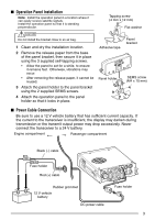
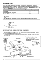
ANTENNA CONNECTION Before operating, you must first install an efficient, well-tuned antenna. The success of your installation will depend largely on the type of antenna and its correct installation. The transceiver can give excellent results if the antenna system and its installation are given careful attention. Use a low-loss coaxial feed line that also has a characteristic impedance of 50 , to match the transceiver input impedance. Coupling the antenna to the transceiver via feed lines having an impedance other than 50 reduces the efficiency of the antenna system and can cause interference to nearby broadcast television receivers, radio receivers, and other electronic equipment. ◆ Transmitting without first connecting an antenna or other matched load may damage the transceiver. Always connect the antenna to the transceiver before transmitting. ◆ All fixed stations should be equipped with a lightning arrester to reduce the risk of fire, electric shock, and/or transceiver damage. Antenna terminal Feed line connector To antenna ACCESSORY CONNECTIONS ■ External Speakers If you plan to use external speakers, choose speakers with an impedance of 4 to 8 (standard is 8 ). The external speaker jacks accept a 3.5 mm (1/8") mono (2-conductor) plug. There are 2 speaker jacks on the rear of the transceiver: SP 1 and SP 2. SP 1 jack SP 2 jack External speakers 7
-
 1
1 -
2
-
3
-
4
-
5
-
6
-
7
-
8
-
9
-
 10
10 -
 11
11 -
 12
12 -
 13
13 -
 14
14 -
 15
15 -
 16
16 -
 17
17 -
 18
18 -
 19
19 -
 20
20 -
21
-
22
-
23
-
24
-
25
-
26
-
27
-
28
-
29
-
30
-
31
-
32
-
33
-
34
-
35
-
36
-
37
-
38
-
39
-
40
-
41
-
42
-
43
-
44
-
45
-
46
-
47
-
48
-
49
-
50
-
51
-
52
-
53
-
54
-
55
-
56
-
57
-
58
-
59
-
60
-
61
-
62
-
63
-
64
-
65
-
66
-
67
-
68
-
69
-
70
-
71
-
72
-
73
-
74
-
75
-
76
-
77
-
78
-
79
-
80
-
81
-
82
-
83
-
84
-
85
-
86
-
87
-
88
-
89
-
90
-
91
-
92
-
93
-
94
-
95
-
96
-
97
-
98
-
99
-
100
-
101
-
102
-
103
-
104
-
105
-
106
-
107
-
108
-
109
-
110
-
111
-
112
-
113
-
114
-
115
-
116
-
117
-
118
-
119
-
120
-
121
-
122
-
123
-
124
-
125
-
126
-
127
-
128
-
129
-
130
-
131
-
132
-
133
-
134
-
135
-
136
-
137
-
138
-
139
-
140
-
141
-
142
-
143
-
144
-
145
-
146
-
147
-
148
-
149
-
150
-
151
-
152
-
153
-
154
-
155
-
156
-
157
-
158
-
159
-
160
 |
 |
