Kenwood TM-D710GE Instruction Manual 1 - Page 11
Operation Panel Installation, Power Cable Connection
 |
View all Kenwood TM-D710GE manuals
Add to My Manuals
Save this manual to your list of manuals |
Page 11 highlights
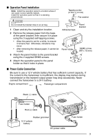
■ Operation Panel Installation Note: Install the operation panel in a location where it can easily receive satellite signals. Install the operation panel so that it is standing perpendicular. Tapping screw (4 mm x 12 mm) Flat washer Do not install the bracket close to an air bag. 1 Clean and dry the installation location. 2 Remove the release paper from the base of the panel bracket, then secure it in place using the 3 supplied self-tapping screws. • Allow the panel to set for a while, to ensure it remains fast. Otherwise, vibrations may occur. • After removing the release paper, it cannot be reused. 3 Attach the panel holder to the panel bracket using the 2 supplied SEMS screws. 4 Attach the operation panel to the panel holder so that it locks in place. Adhesive tape Panel holder Panel bracket SEMS screw (M4 x 10 mm) ■ Power Cable Connection Be sure to use a 12 V vehicle battery that has sufficient current capacity. If the current to the transceiver is insufficient, the display may darken during transmission or the transmit output power may drop excessively. Never connect the transceiver to a 24 V battery. Engine compartment Passenger compartment Black (r) cable Fuse holder Red (+) cable Rubber grommet 12 V vehicle battery DC power cable Fuse holder 3
-
 1
1 -
2
-
3
-
4
-
5
-
 6
6 -
 7
7 -
 8
8 -
 9
9 -
 10
10 -
 11
11 -
 12
12 -
 13
13 -
 14
14 -
 15
15 -
 16
16 -
17
-
18
-
19
-
20
-
21
-
22
-
23
-
24
-
25
-
26
-
27
-
28
-
29
-
30
-
31
-
32
-
33
-
34
-
35
-
36
-
37
-
38
-
39
-
40
-
41
-
42
-
43
-
44
-
45
-
46
-
47
-
48
-
49
-
50
-
51
-
52
-
53
-
54
-
55
-
56
-
57
-
58
-
59
-
60
-
61
-
62
-
63
-
64
-
65
-
66
-
67
-
68
-
69
-
70
-
71
-
72
-
73
-
74
-
75
-
76
-
77
-
78
-
79
-
80
-
81
-
82
-
83
-
84
-
85
-
86
-
87
-
88
-
89
-
90
-
91
-
92
-
93
-
94
-
95
-
96
-
97
-
98
-
99
-
100
-
101
-
102
-
103
-
104
-
105
-
106
-
107
-
108
-
109
-
110
-
111
-
112
-
113
-
114
-
115
-
116
-
117
-
118
-
119
-
120
-
121
-
122
-
123
-
124
-
125
-
126
-
127
-
128
-
129
-
130
-
131
-
132
-
133
-
134
-
135
-
136
-
137
-
138
-
139
-
140
-
141
-
142
-
143
-
144
-
145
-
146
-
147
-
148
-
149
-
150
-
151
-
152
-
153
-
154
-
155
-
156
-
157
-
158
-
159
-
160
 |
 |
