JVC GM-X50U Instruction Manual - Page 11
Connections, Precautions, Available Signals
 |
View all JVC GM-X50U manuals
Add to My Manuals
Save this manual to your list of manuals |
Page 11 highlights
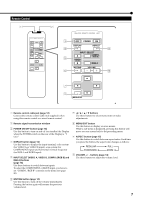
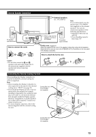
Connections Precautions • Before making connections, turn off all the equipment. • Use a cord whose plugs are correctly matching for the terminals on this Display and the equipment. • Plugs should be firmly inserted; poor connection could cause noise. • To unplug a cord, be sure to grasp its plug and pull it out. • Connect the power cord after having finished all other connections. • Refer also to the user manual of each piece of equipment. Available Signals Video signals The following signals can be input to this Display: • VIDEO A and VIDEO B terminals accept - NTSC, PAL M, and PAL N signals. • COMPONENT/RGB B terminals accept - 480i, 576i, 480p, 576p, 720/60p, 720/50p, 1080/60i (1035/60i), and 1080/50i signals. (You need to set "COMPO./RGB B" to "COMPO." on the menu (see page 20). Computer signals (Preset) This Display has 27 preset video modes for the most popular industrial standard, and the signals of the following image resolutions can be input to the RGB input terminals. No. Signal name 1 PC98 2 VGA400-70 3 VGA480-60 4 WVGA-60 5 VGA480-72 6 VGA480-75 7 SVGA-56 8 SVGA-60 9 SVGA-72 10 SVGA-75 11 XGA-60 12 WXGA-60 13 XGA-70 14 XGA-75 15 XGA-85 16 XGA+-75 17 SXGA-60 18 SXGA-75 19 UXGA-60 20 UXGA-65 21 UXGA-70 22 MAC13" 23 MAC16" 24 MAC19" 25 MAC21" 26 RGB15K-60 27 RGB15K-50 Screen resolution Horizontal 640 640 640 852 640 640 800 800 800 800 1024 1366 1024 1024 1024 1152 1280 1280 1600 1600 1600 640 832 1024 1152 - - Vertical 400 400 480 480 480 480 600 600 600 600 768 768 768 768 768 864 1024 1024 1200 1200 1200 480 624 768 870 - - Horizontal Frequency (kHz) 24.8 31.5 31.5 31.7 37.9 37.5 35.2 37.9 48.1 46.9 48.4 48.4 56.5 60.0 68.7 67.5 64.0 80.0 75.0 81.3 87.5 35.0 49.7 60.2 68.7 15.7 15.6 Vertical Frequency (Hz) 56.4 70.1 59.9 60.3 72.8 75.0 56.3 60.3 72.2 75.0 60.0 60.0 70.1 75.0 85.0 75.0 60.0 75.0 60.0 65.0 70.0 66.7 74.6 74.9 75.1 59.9 50.0 Scan system Non-interlace Non-interlace Non-interlace Non-interlace Non-interlace Non-interlace Non-interlace Non-interlace Non-interlace Non-interlace Non-interlace Non-interlace Non-interlace Non-interlace Non-interlace Non-interlace Non-interlace Non-interlace Non-interlace Non-interlace Non-interlace Non-interlace Non-interlace Non-interlace Non-interlace Interlace Interlace Notes: • When a signal other than listed above is input, a part of the screen may become void or an unnecessary picture may appear. • Signals, though they are within the acceptable range of frequencies, may not be displayed normally, depending on the signal type. • Depending on the connected equipment, the Display may not be compatible with composite sync (Cs) or G on sync signals. • When a preset mode signal is input, the vertical frequency displayed on the screen will have an "*" shown at its right top position. • When the No. 3 and No. 11 signals are input, set "SAMPLING MODE" to "STD" on the menu (see page 25). • When the No. 4 and No. 12 signals are input, make the following settings: - Set "SAMPLING MODE" to "WIDE" on the menu (see page 25). - Change the aspect ratio to "FULL" (see pages 15 and 19). • When No. 16 to No. 21 and No. 25 signals are input, thin lines may become obscure for their signal frequencies are higher than the screen resolution. Using the RGB A input terminals makes the lines clearer than using the RGB B input terminals. • The adjustment of the screen size and position is the setting common to the No. 14 and No. 24 signals. If you use both signals by switching them, the adjustment of either signal may not be proper. 10
-
 1
1 -
2
-
3
-
4
-
5
-
 6
6 -
 7
7 -
 8
8 -
 9
9 -
 10
10 -
 11
11 -
 12
12 -
 13
13 -
 14
14 -
 15
15 -
 16
16 -
17
-
18
-
19
-
20
-
21
-
22
-
23
-
24
-
25
-
26
-
27
-
28
-
29
-
30
-
31
-
32
-
33
-
34
-
35
-
36
-
37
-
38
-
39
-
40
-
41
-
42
-
43
 |
 |
