Invacare GHS350 Owners Manual - Page 12
Attaching/Adjusting the Knee Pad, Attaching the Base Shifter Handle
 |
View all Invacare GHS350 manuals
Add to My Manuals
Save this manual to your list of manuals |
Page 12 highlights
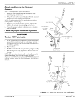
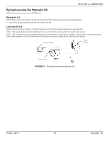
SECTION 2-ASSEMBLY Attaching/Adjusting the Knee Pad NOTE: For this procedure, refer to FIGURE 2.3. ƽ WARNING Never adjust knee pad while patient is in the standing position or while the lift is moving. Always make sure that the adjustment pins are fully engaged in the height adjustment holes before use. Knee Pad Adjustment Pin (1 of 2) 1. Pick a height setting that will be comfortable to the patient and provide the necessary support. NOTE: The knee pad should be positioned so that the knee portion of the leg contacts the pad. NOTE: The upper adjustment pins are typically used for shorter individuals. The lower adjustment pins are typically used for taller individuals. 2. Using both hands, pull both adjustment pins outward at the same time and hold. 3. Position the knee pad to the desired height and release adjustment pins into the corresponding alignment holes. 4. Check to make sure that both pins are engaged. FIGURE 2.3 Attaching/Adjusting the Knee Pad Attaching the Base Shifter Handle NOTE: For this procedure, refer to FIGURE 2.4. 1. Insert the base shifter handle into the cam lock assembly at the back of the base. 2. Align the holes of the shifter handle and cam lock assembly. 3. Tighten the thumbscrew to secure the shifter handle in place. NOTE: This should prevent the base shifter handle from being removed. Thumbscrew Base Shifter Handle Get-U-Up™ Lift Cam Lock Assembly FIGURE 2.4 Attaching the Base Shifter Handle 12 Part No 1148115
-
 1
1 -
2
-
3
-
4
-
5
-
6
-
 7
7 -
 8
8 -
 9
9 -
 10
10 -
 11
11 -
 12
12 -
 13
13 -
 14
14 -
 15
15 -
 16
16 -
 17
17 -
18
-
19
-
20
-
21
-
22
-
23
-
24
-
25
-
26
-
27
-
28
 |
 |
