Invacare GHS350 Owners Manual - Page 10
ASSEMBLy, Attach the Mast to the Base Assembly, WARNING
 |
View all Invacare GHS350 manuals
Add to My Manuals
Save this manual to your list of manuals |
Page 10 highlights
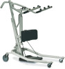
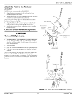
SECTION 2-ASSEMBLY SECTION 2-ASSEMBLY ƽ WARNING Each time the mast is removed and assembled to the base assembly, the mast MUST be locked into the socket of the base assembly. Attach the Mast to the Base Assembly NOTE: For this procedure, refer to FIGURE 2.1. 1. Remove the locking screw from the base assembly. 2. Match the notch at the bottom of the mast with the tabs inside the socket of the base assembly. 3. Insert the mast into the socket and onto the tabs. 4. Try to turn the mast. NOTE: If the mast turns in the socket, repeat STEPS 2 and 3 until proper alignment is obtained. 5. If the mast does not turn in the socket, insert the locking screw into the base and tighten securely. Side view of the Base Assembly and Mast Notch Locking Screw Mast Socket Tab FIGURE 2.1 Attach the Mast to the Base Assembly Get-U-Up™ Lift 10 Part No 1148115
-
 1
1 -
2
-
3
-
4
-
 5
5 -
 6
6 -
 7
7 -
 8
8 -
 9
9 -
 10
10 -
 11
11 -
 12
12 -
 13
13 -
 14
14 -
 15
15 -
16
-
17
-
18
-
19
-
20
-
21
-
22
-
23
-
24
-
25
-
26
-
27
-
28
 |
 |
