Invacare 9805 Owners Manual - Page 18
Base Shifter Handle Assembly, Swivel Bar Attachment with Mounting Bracket
 |
View all Invacare 9805 manuals
Add to My Manuals
Save this manual to your list of manuals |
Page 18 highlights
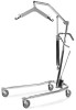
SECTION 4-ASSEMBLY Base Shifter Handle Assembly NOTE: For this procedure, refer to FIGURE 4.3. 1. Insert the base shifter handle into the cam lock assembly at the back of the base. 2. Align the holes of the shifter handle and cam lock assembly. 3. Tighten the thumbscrew to secure the shifter handle in place. NOTE: This should prevent the base shifter handle from being removed. Base Shifter Handle Thumbscrew Cam Lock Assembly FIGURE 4.3 Base Shifter Handle Assembly Swivel Bar Attachment with Mounting Bracket NOTE: For this procedure, refer to FIGURE 4.4. 1. Push the pin and washers up through the swivel bar pad. 2. Line-up hole in pin with mounting bracket holes and secure with shoulder screw and nut provided. NOTE: The swivel bar has hooks on both ends to accept the hardware used to attach the sling that supports the patient during lift. The swivel bar pad should remain in place during normal use. NOTE: Make sure Pin and Washers are completely pushed up through the Swivel Bar Pad. Nut Pin Shoulder Screw Swivel Bar Pad FIGURE 4.4 Swivel Bar Attachment with Mounting Bracket Portable Patient Lift and Sling 18 Part No 1024492
-
 1
1 -
2
-
3
-
4
-
5
-
6
-
7
-
8
-
9
-
10
-
11
-
12
-
 13
13 -
 14
14 -
 15
15 -
 16
16 -
 17
17 -
 18
18 -
 19
19 -
 20
20 -
 21
21 -
 22
22 -
 23
23 -
24
-
25
-
26
-
27
-
28
-
29
-
30
-
31
-
32
-
33
-
34
-
35
-
36
-
37
-
38
-
39
-
40
-
41
-
42
-
43
-
44
 |
 |
