Invacare 5890IVC Owners Manual - Page 26
Assembling/Installing/Removing Drive, Shaft
 |
View all Invacare 5890IVC manuals
Add to My Manuals
Save this manual to your list of manuals |
Page 26 highlights
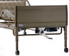
Invacare® Homecare Beds 4.10 Assembling/Installing/Removing Drive Shaft Reverse this procedure to remove the drive shaft. The drive shaft for Hi/Lo function consists of two sections that are shipped unassembled. The inner drive shaft has a positioning spring button, and the outer drive shaft has multiple holes and a spring-loaded end. 3. Engage the spring button into the third positioning hole D. 4. Push in on the spring loaded end of the drive shaft E and attach to the Hi/Lo motor F output shaft G. 1. Remove the plastic caps from each end of the drive shaft. 2. Press the spring button A on the inner drive shaft B and insert the inner drive shaft into the outer drive shaft C. 5. Attach the drive shaft to the gear box head end H (bottom opening) at the head end of the bed. 6. Ensure the Hi/Lo motor output shaft spring-loaded coupler is properly aligned with the foot end gear box. 26 1114836-H-05
-
 1
1 -
2
-
3
-
4
-
5
-
6
-
7
-
8
-
9
-
10
-
11
-
12
-
13
-
14
-
15
-
16
-
17
-
18
-
19
-
20
-
 21
21 -
 22
22 -
 23
23 -
 24
24 -
 25
25 -
 26
26 -
 27
27 -
 28
28 -
 29
29 -
 30
30 -
 31
31 -
32
-
33
-
34
-
35
-
36
-
37
-
38
-
39
-
40
-
41
-
42
-
43
-
44
-
45
-
46
-
47
-
48
 |
 |
