Intermec IF61 GPIO Terminal Block User's Guide
Intermec IF61 Manual
 |
View all Intermec IF61 manuals
Add to My Manuals
Save this manual to your list of manuals |
Intermec IF61 manual content summary:
- Intermec IF61 | GPIO Terminal Block User's Guide - Page 1
GPIO Terminal Block IF5, IF30, IF61, IV7 User's Guide - Intermec IF61 | GPIO Terminal Block User's Guide - Page 2
intermec.com The information contained herein is provided solely for the purpose of allowing customers to operate and service Intermec Intermec Technologies Corporation. © 2007-2010 by Intermec Technologies Corporation. All rights reserved. The word Intermec, the Intermec of Intermec Technologies - Intermec IF61 | GPIO Terminal Block User's Guide - Page 3
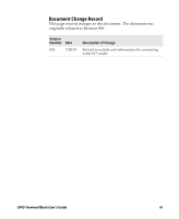
Document Change Record This page records changes to this document. The document was originally released as Revision 001. Version Number Date 002 7/2010 Description of Change Revised to include new information for connecting to the IV7 reader. GPIO Terminal Block User's Guide iii - Intermec IF61 | GPIO Terminal Block User's Guide - Page 4
iv GPIO Terminal Block User's Guide - Intermec IF61 | GPIO Terminal Block User's Guide - Page 5
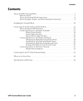
IF61 Readers 12 About the Reader GPIO Interface 12 Connecting Devices to the Input Terminals 12 Reader 17 Switching the High Side Using Reader Power 18 Switching the Low Side Using Reader Power 19 Switching the High Mount Reader 23 Where to Go From Here 24 Specifications and Pinouts - Intermec IF61 | GPIO Terminal Block User's Guide - Page 6
Contents 6 GPIO Terminal Block User's Guide - Intermec IF61 | GPIO Terminal Block User's Guide - Page 7
Intermec RFID readers. GPIO Terminal Block What You Need You connect the terminal block to the reader with a GPIO cable: • For IF5, IF30, and IF61, use Intermec P/N 236-057-001. • For IV7, use Intermec IF61 Readers" on page 12. Note: Using the terminal block with the IV7 Vehicle-Mount Reader - Intermec IF61 | GPIO Terminal Block User's Guide - Page 8
Connections Connect the terminal block to your Intermec reader through the serial port. Cables from to connect industrial control wiring to the reader GPIO and power interfaces. Note: The more information, see "Connecting To the IV7 Vehicle-Mount Reader" on page 23. The screw terminals are located - Intermec IF61 | GPIO Terminal Block User's Guide - Page 9
Connections: This illustration shows the input, output, and power terminal connections on the main circuit board. Note: To use the terminal block with the IV7 reader, remove the jumpers from the Output terminals. For more information, see "Connecting To the IV7 Vehicle-Mount - Intermec IF61 | GPIO Terminal Block User's Guide - Page 10
the terminal block in the location and secure it to the mounting surface with four appropriate fasteners. Mounting hardware (4 places) 10 GPIO Terminal Block User's Guide - Intermec IF61 | GPIO Terminal Block User's Guide - Page 11
only). 8 Install the top cover. 9 Connect the GPIO cable to the terminal block serial port and to the reader as follows: • For the IF61, connect the cable (P/N 236-057-001) to the GPIO port. • For the IF5 or IF30, connect and to the COM port on the host PC. GPIO Terminal Block User's Guide 11 - Intermec IF61 | GPIO Terminal Block User's Guide - Page 12
a schematic, see "Connecting To the IV7 Vehicle-Mount Reader" on page 23. About the Reader GPIO Interface The IF5, IF30, and IF61 readers have four general purpose input and output interfaces. Each four terminal posts: • 12 V • +Input • -Input • Gnd (Ground) 12 GPIO Terminal Block User's Guide - Intermec IF61 | GPIO Terminal Block User's Guide - Page 13
Reader Interface Reader CPU 12 VDC - + +12 V +Input -Input Ground Input Terminal Schematic: This illustration shows a reader depends on the RFID application being used in the system. Typically, the reader senses input with power from the reader. • Isolate the reader from the input power source - Intermec IF61 | GPIO Terminal Block User's Guide - Page 14
Powered Input Supplying the input interface with power from the reader is the easiest way to connect a control to an input to the +12 V post as shown in the next illustration. Reader interface Input RTN +12 V +Input External input switch Reader Powered Input 14 GPIO Terminal Block User - Intermec IF61 | GPIO Terminal Block User's Guide - Page 15
induced noise by referencing a remote input to chassis return of the reader. Use a twisted pair cable to connect the input device to the 12 VDC power from the reader or the reference chassis ground. The next illustration shows how this input method is wired. Reader interface Input RTN Isolated Input - Intermec IF61 | GPIO Terminal Block User's Guide - Page 16
noise, follow good grounding practices for both the reader and the input device. The illustration shows the reader providing power to the pull-up resistor for to short out the +12 V and +Input posts. Reader interface 12 V Input RTN Open Collector Input Interface Input (< 6 mA) Ground - Intermec IF61 | GPIO Terminal Block User's Guide - Page 17
reader. Each output is optically isolated from the reader, polarized, and rated for 5 to 48 VDC at 0.25 A. All reader - + Reader interface Indicator LED +12 V +Output -Output (125 mA max.) Ground Reader Output Terminal outputs are used depends on the RFID application software being used in the - Intermec IF61 | GPIO Terminal Block User's Guide - Page 18
from the reader or from an reader. • Switching the low side, with the load powered by the reader reader. Only the single output being switched is affected if the interface cable fails. This configuration supports many indicator lamp applications. By default next illustration. Reader interface 12 V - Intermec IF61 | GPIO Terminal Block User's Guide - Page 19
, use the jumper to short the -Output and Ground posts together as shown in the next illustration. Reader interface +12 V External indicator lamp (max. 2) 0.25 A maximum +Output Switching the Low Side of create some confusion with maintenance activity. GPIO Terminal Block User's Guide 19 - Intermec IF61 | GPIO Terminal Block User's Guide - Page 20
load, remove the output terminal jumper. You should also connect the reader ground to the ground system of the external power supply, which indicator lamp Switching the High Side With External Power Note: If the reader ground is not connected to the external power ground, the output terminal - Intermec IF61 | GPIO Terminal Block User's Guide - Page 21
code regulations. Connecting Devices to the Power Terminal The power terminal provides access to DC power from the reader (except for IV7). The GPIO interface provides a total of 12 VDC at 0.5 A for powering Ground posts on the input and output terminals. GPIO Terminal Block User's Guide 21 - Intermec IF61 | GPIO Terminal Block User's Guide - Page 22
sensors as inputs and indicator lamps as outputs. All are connected to the power terminal on the terminal block and powered by the reader. Position detection sensor Position detection sensor Inputs Outputs +12 V +Input -Output Ground TB2 TB6 +12 V +Input -Output Ground TB1 TB5 Output - Intermec IF61 | GPIO Terminal Block User's Guide - Page 23
Connecting To the IV7 Vehicle-Mount Reader Connecting GPIO devices to the IV7 reader requires special considerations. The IV7 GPIO: • inputs are limited to 40 mA total. • outputs are limited to not connect the IV7 to any other terminals in the terminal block. GPIO Terminal Block User's Guide 23 - Intermec IF61 | GPIO Terminal Block User's Guide - Page 24
reader, see the reader user's manual. You may need additional information when working with the reader in your data collection system. To download PDF files of our current manuals, visit www.intermec.com and choose Support > Manuals IF61 GPIO Port Pin 13 Pin 1 Pin 25 Pin 14 24 GPIO Terminal - Intermec IF61 | GPIO Terminal Block User's Guide - Page 25
Port Pin Assignments for Terminal Block, IF5, IF30, and IF61 Pin Description 1 -Input 1 2 -Input 2 3 -Input 3 4 -Input 4 5 Ground 6 Ground 7 +Output IF61 only) High, 10 to 48 V (10 to 36 V for IF61 only) High, 10 to 48 V (10 to 36 V for IF61 only) High, 10 to 48 V (10 to 36 V for IF61 - Intermec IF61 | GPIO Terminal Block User's Guide - Page 26
3 14 GPIO Return 4 15 GPIO Return 5 16 NC 17 GP Output 0 18 GP Output 1 19 GP Output 2 20 GP Output 3 26 GPIO Terminal Block User's Guide - Intermec IF61 | GPIO Terminal Block User's Guide - Page 27
GPIO Terminal Block User's Guide 27 - Intermec IF61 | GPIO Terminal Block User's Guide - Page 28
Worldwide Headquarters 6001 36th Avenue West Everett, Washington 98203 U.S.A. tel 425.348.2600 fax 425.355.9551 www.intermec.com © 2010 Intermec Technologies Corporation. All rights reserved. GPIO Terminal Block User's Guide *934-001-002* P/N 934-001-002
-
 1
1 -
 2
2 -
 3
3 -
 4
4 -
 5
5 -
 6
6 -
 7
7 -
8
-
9
-
10
-
11
-
12
-
13
-
14
-
15
-
16
-
17
-
18
-
19
-
20
-
21
-
22
-
23
-
24
-
25
-
26
-
27
-
28
 |
 |
GPIO
Terminal Block
IF5, IF30, IF61, IV7
User’s
Guide