Intel BOXD850EMD2L Product Specification - Page 24
RDRAM Memory Configuration
 |
UPC - 735858154024
View all Intel BOXD850EMD2L manuals
Add to My Manuals
Save this manual to your list of manuals |
Page 24 highlights
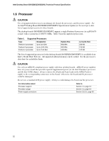
Intel Desktop Board D850EMD2/D850EMV2 Technical Product Specification 1.7.3 RDRAM Memory Configuration When installing memory, note the following: • The four RIMM sockets are grouped into two banks: Bank 0 (labeled on the board as RIMM1 and RIMM2) Bank 1 (labeled on the board as RIMM3 and RIMM4) • Bank 0 must be populated first, ensuring that the RDRAM installed in RIMM1 and RIMM2 is identical in speed, size, and density. For example, the minimum system configuration would use two 64 MB RIMM modules of PC800 RDRAM. • If the desired memory configuration has been achieved by populating Bank 0, then Bank 1 should be filled with two Continuity RIMMs. • If memory is to be installed in Bank 1, the RIMM modules installed in RIMM3 and RIMM4 must be identical in size and density to each other and match the speed of the RIMM modules in Bank 0. The RIMM modules do not, however, need to match those in Bank 0 in size and density. For example, if Bank 0 has two 128 MB RIMMs of PC800 RDRAM, Bank 1 would require PC800 RDRAM also; however, any other supported RIMM modules such as 64 MB or 192 MB could be used. • If ECC functionality is required, all installed RIMM modules must be ECC compliant. Table 6 gives examples of RDRAM component density for various RIMM modules. Component density (counts) can be identified on the RIMM label. Table 6. Supported Memory Configurations Rambus Technology Capacity with 4 DRAM Components per RIMM Capacity with 6 DRAM Components per RIMM 128/144 Mbit, -40 64 MB 96 MB 256/288 Mbit, -40 128 MB 192 MB Capacity with 8 DRAM Components per RIMM 128 MB 256 MB Capacity with 12 DRAM Components per RIMM 192 MB 384 MB Capacity with 16 DRAM Components per RIMM 256 MB 512 MB CAUTION If the installed processor operates with a 533 MHz system bus, use only PC800-40 memory; do not use PC800-45 memory. Failure to follow this guideline may result in unreliable operation. If the installed processor operates with a 400 MHz system bus, you can use either PC800-40 or PC800-45 memory. Table 7 lists the supported combinations of memory types with processor system bus values. Table 7. Memory Support Matrix Processor System Bus 533 MHz 400 MHz Support for PC800-40 memory? Yes Yes Support for PC800-45 memory? No Yes Note: Will default to PC600-level performance. Support for PC700 memory? No (Note) Support for PC600 memory? No Yes 24
-
 1
1 -
2
-
3
-
4
-
5
-
6
-
7
-
8
-
9
-
10
-
11
-
12
-
13
-
14
-
15
-
16
-
17
-
18
-
 19
19 -
 20
20 -
 21
21 -
 22
22 -
 23
23 -
 24
24 -
 25
25 -
 26
26 -
 27
27 -
 28
28 -
 29
29 -
30
-
31
-
32
-
33
-
34
-
35
-
36
-
37
-
38
-
39
-
40
-
41
-
42
-
43
-
44
-
45
-
46
-
47
-
48
-
49
-
50
-
51
-
52
-
53
-
54
-
55
-
56
-
57
-
58
-
59
-
60
-
61
-
62
-
63
-
64
-
65
-
66
-
67
-
68
-
69
-
70
-
71
-
72
-
73
-
74
-
75
-
76
-
77
-
78
-
79
-
80
-
81
-
82
-
83
-
84
-
85
-
86
-
87
-
88
-
89
-
90
-
91
-
92
-
93
-
94
-
95
-
96
-
97
-
98
-
99
-
100
-
101
-
102
-
103
-
104
-
105
-
106
-
107
-
108
-
109
-
110
-
111
-
112
-
113
-
114
-
115
-
116
-
117
-
118
-
119
-
120
-
121
-
122
-
123
-
124
-
125
-
126
 |
 |
