Image Fitness 3.0 Bench English Manual - Page 7
Adjustment
 |
View all Image Fitness 3.0 Bench manuals
Add to My Manuals
Save this manual to your list of manuals |
Page 7 highlights
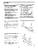
3. Slide the Frame (4) through the tube on the 3 Crossbar (3). Tighten the Short Knob (29) into the indicated location on the Crossbar. See the inset drawing. Slide the M10 x 65mm Bolt (25) through the indicated hole and tighten an M10 Nylon Locknut (22) onto the Bolt. 4. Attach both Backrest Tubes (10) to the Backrest 4 (11) with four M6 x 63mm Bolts (20) and four M6 Washers (38). The indicated holes in the Backrest Tubes must be facing up as shown. 4 . • 3 29 . _ 22 4 25 'qv 11 5. Lubricate an M10 x 170mm Bolt (24). Attach the Backrest Tubes (10) to the Frame (4) with the Bolt and an t.110 Ny!on Locknut (22). . 1 . . . : 38 These Holes must be up 20 5 : 38 20 /7/ 22 \• 10 24-Lubricate 6. Slide the Adjustment Bracket (14) onto the Frame (4). Align the indicated hole in the Adjustment 6 Bracket with the welded tube in the Frame. Insert the "L"-Pin (15) through the Adjustment Bracket and the Frame. 0* 4 • • • 4 • . . . 15 14 7
-
 1
1 -
 2
2 -
 3
3 -
 4
4 -
 5
5 -
 6
6 -
 7
7 -
 8
8 -
 9
9 -
 10
10 -
 11
11 -
 12
12 -
13
-
14
-
15
-
16
-
17
-
18
-
19
 |
 |
