HP T1500J HP Uninterruptible Power System T2200 XR Models User Guide - Page 25
Configuration Parameters, Placing the UPS in Con mode, Table 3-1
 |
View all HP T1500J manuals
Add to My Manuals
Save this manual to your list of manuals |
Page 25 highlights
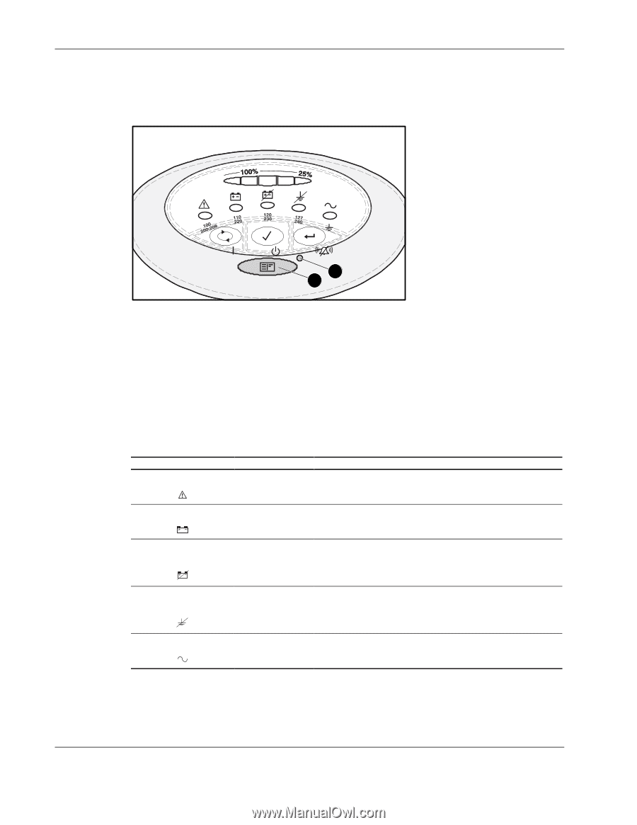
Configuration 2. Press and hold the Configure button (2) for three seconds. When the Configure button is released, the front panel configuration parameters flash in unison and the Configure Mode On LED (1) illuminates solid green. 1 2 Figure 3-2: Placing the UPS in Configure mode Configuration Parameters In Configure mode, the front panel LED display changes function to allow UPS monitoring. The LED control buttons allow modification of the UPS configuration parameters. The configuration parameters are defined in Table 3-1. Available voltage settings per model are listed in Table 3-2. Table 3-1: Configuration Parameters Parameter (LED) General Alarm () Parameter Name 100/200-208 Nom Explanation (when illuminated) Nominal utility voltage level is selected to 100/208 VAC. On Battery 110/220 Nom Nominal utility voltage level is selected to 110/220 VAC. () Bad Battery/Low Battery 120/230 Nom Nominal utility voltage level is selected to 120/230 VAC. () Site Wiring Fault Indicator 127/240 Nom Nominal utility voltage level is selected to 127/240 VAC. () Utility LED () Site Wiring Audible alarm is enabled if ground is missing, or if line Fault Indicator and neutral connections are reversed. 3-2 HP Uninterruptible Power System T2200 XR Models User Guide
-
 1
1 -
2
-
3
-
4
-
5
-
6
-
7
-
8
-
9
-
10
-
11
-
12
-
13
-
14
-
15
-
16
-
17
-
18
-
19
-
 20
20 -
 21
21 -
 22
22 -
 23
23 -
 24
24 -
 25
25 -
 26
26 -
 27
27 -
 28
28 -
 29
29 -
 30
30 -
31
-
32
-
33
-
34
-
35
-
36
-
37
-
38
-
39
-
40
-
41
-
42
-
43
-
44
-
45
-
46
-
47
-
48
-
49
-
50
-
51
 |
 |