HP T1500J HP Uninterruptible Power System T2200 XR Models User Guide - Page 12
Rear Panels, Rear panel of T2200 XR NA
 |
View all HP T1500J manuals
Add to My Manuals
Save this manual to your list of manuals |
Page 12 highlights
Overview Rear Panels The rear panel configurations of the UPS are shown in Figures 1-2, 1-3, 1-4, and 1-5. 1 2 3 4 5 6 8 7 Figure 1-2: Rear panel of T2200 XR NA 1 Communications port/option slot 2 Network Transient Protector IN jack 3 Network Transient Protector OUT jack 4 Load segment 2 (three NEMA 5-15 receptacles) 5 Load segment 1 (three NEMA 5-15 receptacles) 6 Load segment 3 (two NEMA 5-20 receptacles) 7 ERM connector 8 Power cord with NEMA 5-20 plug 1-4 HP Uninterruptible Power System T2200 XR Models User Guide
-
 1
1 -
2
-
3
-
4
-
5
-
6
-
 7
7 -
 8
8 -
 9
9 -
 10
10 -
 11
11 -
 12
12 -
 13
13 -
 14
14 -
 15
15 -
 16
16 -
 17
17 -
18
-
19
-
20
-
21
-
22
-
23
-
24
-
25
-
26
-
27
-
28
-
29
-
30
-
31
-
32
-
33
-
34
-
35
-
36
-
37
-
38
-
39
-
40
-
41
-
42
-
43
-
44
-
45
-
46
-
47
-
48
-
49
-
50
-
51
 |
 |

Overview
1-4
HP Uninterruptible Power System T2200 XR Models User Guide
Rear Panels
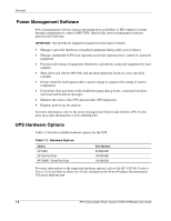
The rear panel configurations of the UPS are shown in Figures 1-2, 1-3, 1-4, and 1-5.
1
3
2
4
5
6
8
7
Figure 1-2:
Rear panel of T2200 XR NA
1
Communications port/option slot
2
Network Transient Protector IN jack
3
Network Transient Protector OUT jack
4
Load segment 2 (three NEMA 5-15 receptacles)
5
Load segment 1 (three NEMA 5-15 receptacles)
6
Load segment 3 (two NEMA 5-20 receptacles)
7
ERM connector
8
Power cord with NEMA 5-20 plug