HP Server Console 0x2x16 HP IP Console Switchwith Virtual Media Installation I - Page 3
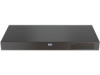
Performing a side-mount type A installation, Secure the console switch to the rails using four self
 |
View all HP Server Console 0x2x16 manuals
Add to My Manuals
Save this manual to your list of manuals |
Page 3 highlights
Performing a side-mount type A installation 1. Remove the four screws, two on each side, from the console switch. 2. Attach the side-mounting brackets to the console switch using the four screws that you removed. Performing a side-mount type B installation 1. Remove the four screws, two on each side, from the console switch. 2. Attach the side-mounting brackets to the console switch using the four screws that you removed. 3. Slide the side-mounting bracket tabs into the U locations on each side of the rack. 3. Slide the side-mounting bracket tabs into the U locations on each side of the rack. 4. Secure the console switch to the rails using four selftapping screws, two on each side. 4. Install four cage nuts into the side-mounting bracket U locations. 5. Secure the console switch to the rails, using four M-6 screws, two on each side.
-
 1
1 -
 2
2 -
 3
3 -
 4
4 -
 5
5
 |
 |
