HP R7000 UPS R12000 XR ERM Installation Instructions - Page 4
Installing the ERM in the Rack
 |
View all HP R7000 manuals
Add to My Manuals
Save this manual to your list of manuals |
Page 4 highlights
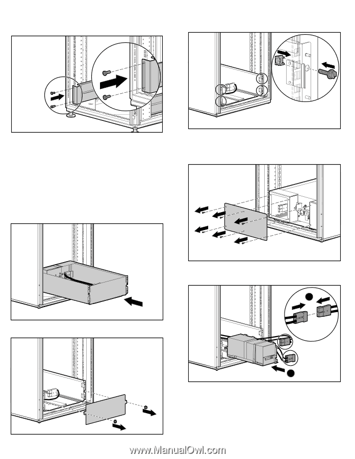
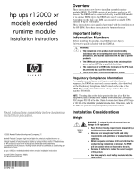
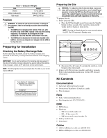
5. Insert the back screws into the cage nuts that were installed in step 3. 5. Secure the chassis to the rack using the screws and cage nuts supplied with the rack. Installing the ERM in the Rack Before attempting to install the ERM, review and adhere to all safety information provided in the "Installation Considerations" section of this document. To install the ERM in the rack: 1. With one person on each side of the carton, remove the ERM chassis from the carton. 2. Gently lower the chassis to the floor in front of the rack. 3. With one person on each side, lift the chassis to rail level and slide into place. NOTE: After installing the ERM chassis, insert remaining screws for additional support, if any screw holes are unoccupied. 6. Remove the electrical access cover on the rear of the ERM chassis. 4. Remove the front panel from the ERM chassis. 7. Insert the left battery module (1) and connect the battery module connector to the connector in the ERM chassis (2). 2 1
-
 1
1 -
 2
2 -
 3
3 -
 4
4 -
 5
5 -
 6
6 -
 7
7
 |
 |