HP R7000 UPS R3000 XR Models User Guide - Page 22
Operation, Front Panel Controls and LED Indicators
 |
View all HP R7000 manuals
Add to My Manuals
Save this manual to your list of manuals |
Page 22 highlights
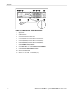
2 Operation This chapter contains information on operating the UPS. Topics include the front panel controls, LED indicators, and modes of operation. Knowledge of these features is helpful when configuring and troubleshooting the unit. NOTE: For installation considerations and procedures, refer to the instructions included with the UPS. Copies of this document can be downloaded from www.hp.com. Front Panel Controls and LED Indicators The front panel controls and LED indicators provide an easy-to-use interface for UPS configuration and monitoring. 6 7 8 9 10 15 1 2 3 4 14 5 13 12 11 Figure 2-1: Front panel controls and LED indicators Item Description Meaning/Function 1 Overload LED Red-UPS load exceeds maximum power available. 2 76% to 100% load Green-UPS load is approximately 76% to 100% of maximum power. 3 51% to 75% load Green-UPS load is approximately 51% to 75% of maximum power. 4 26% to 50% load Green-UPS load is approximately 26% to 50% of maximum power. 5 0% to 25% load Green-UPS load is approximately 0% to 25% of maximum power. 6 General Alarm Red-UPS detected a general alarm. Perform a self-test. continued HP Uninterruptible Power System R3000 XR Models User Guide 2-1
-
 1
1 -
2
-
3
-
4
-
5
-
6
-
7
-
8
-
9
-
10
-
11
-
12
-
13
-
14
-
15
-
16
-
 17
17 -
 18
18 -
 19
19 -
 20
20 -
 21
21 -
 22
22 -
 23
23 -
 24
24 -
 25
25 -
 26
26 -
 27
27 -
28
-
29
-
30
-
31
-
32
-
33
-
34
-
35
-
36
-
37
-
38
-
39
-
40
-
41
-
42
-
43
-
44
-
45
-
46
-
47
-
48
-
49
-
50
-
51
-
52
-
53
-
54
-
55
-
56
-
57
-
58
-
59
-
60
-
61
 |
 |
