HP Indigo 7500 Side Fog Troubleshooting - Page 8
Catch tray, Imaging oil tubes, Imaging oil reservoir, DFS (Dynamic Flow System)
 |
View all HP Indigo 7500 manuals
Add to My Manuals
Save this manual to your list of manuals |
Page 8 highlights
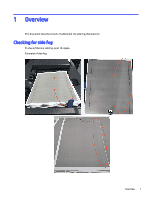
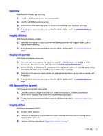
Catch tray Refer below for cleaning the Catch tray. 1. Clean the catch tray that is under the cleaning station. 2. Check for and tighten any loose screws. 3. At the bottom of the catch tray, verify the condition of the sponge layer. Replace if necessary. 4. If any corrective action was taken above, check for side fog as described in "Checking for side fog on page 1". Imaging oil tubes Refer below for Imaging oil tubes. 1. Verify that the imaging oil tubes to and from the cleaning station are not clogged or bent. Clean or replace them if necessary. 2. If any corrective action was taken above, check for side fog as described in "Checking for side fog on page 1". Imaging oil reservoir Refer below for Imaging oil reservoir. 1. Verify that there is no extensive foaming in the reservoir. If there is, replace the imaging oil in the reservoir and then check for side fog as described in "Checking for side fog on page 1". 2. Measure imaging oil conductivity. It should not be below 2 pmho. If it is below 2, check the silica pump as described in TN-1724 - Dripping and Side Fog on Print and act accordingly. 3. Verify that all the reservoir in/out tubes are not leaking or blocked (bent or dirty). Clean or replace them if necessary. 4. If any corrective action was taken above, check for side fog as described in "Checking for side fog on page 1". DFS (Dynamic Flow System) Refer below for the Dynamic Flow System. 1. Check the condition and operation of the DFS. If there are any failures, fix them as described in CA393-05200 - Dynamic Flow System (DFS) troubleshooting procedures. 2. If any corrective action was taken above, check for side fog as described in "Checking for side fog on page 1". Imaging oil flow Refer below for Imaging oil flow. 1. If there is a DFS, bypass it. 2. Perform the Cleaning Station Flow Calibration wizard manually and verify that the cleaning station imaging oil flow is 4.2 L/m. 3. Check for side fog as described in "Checking for side fog on page 1". Catch tray 5
-
 1
1 -
2
-
 3
3 -
 4
4 -
 5
5 -
 6
6 -
 7
7 -
 8
8 -
 9
9 -
 10
10 -
 11
11 -
 12
12 -
 13
13 -
14
-
15
-
16
 |
 |
