HP Chromebook 14-da0000 x360 Maintenance and Service Guide - Page 24
Removal and replacement procedures, Preparation for disassembly, Computer feet and bottom cover
 |
View all HP Chromebook 14-da0000 x360 manuals
Add to My Manuals
Save this manual to your list of manuals |
Page 24 highlights
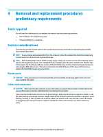
5 Removal and replacement procedures CAUTION: Components described in this chapter should only be accessed by an authorized service provider. Accessing these parts can damage the computer or void the warranty. NOTE: HP continually improves and changes product parts. For complete and current information on supported parts this your computer, go to http://partsurfer.hp.com, select your country or region, and then follow the on-screen instructions. Component replacement procedures There are as many as 40 screws that must be removed, replaced, and/or loosened when servicing the computer. Make special note of each screw size and location during removal and replacement. Preparation for disassembly See Removal and replacement procedures preliminary requirements on page 14 for initial safety procedures. 1. Turn off the computer. If you are unsure whether the computer is off or in Sleep state, turn the computer on, and then shut it down through the operating system. 2. Disconnect the power from the computer by unplugging the power cord from the computer. 3. Disconnect all external devices from the computer Computer feet and bottom cover Description Computer feet (included in the rubber kit) Bottom cover Spare part number L36890-001 L36891-001 Remove the computer feet and bottom cover: 1. Prepare the computer for disassembly (Preparation for disassembly on page 18). 2. Close the computer and position it upside down. 3. Peel the two rubber feet off the computer (1). 4. Remove the five Phillips M2.5×8.0 screws (2) from under the feet. 18 Chapter 5 Removal and replacement procedures
-
 1
1 -
2
-
3
-
4
-
5
-
6
-
7
-
8
-
9
-
10
-
11
-
12
-
13
-
14
-
15
-
16
-
17
-
18
-
 19
19 -
 20
20 -
 21
21 -
 22
22 -
 23
23 -
 24
24 -
 25
25 -
 26
26 -
 27
27 -
 28
28 -
 29
29 -
30
-
31
-
32
-
33
-
34
-
35
-
36
-
37
-
38
-
39
-
40
-
41
-
42
-
43
-
44
-
45
-
46
-
47
-
48
-
49
-
50
-
51
-
52
-
53
-
54
-
55
 |
 |
