Gigabyte GZ-FW1CA-AJS User Manual - Page 21
ond splitter on the 4-way splitter valve
 |
View all Gigabyte GZ-FW1CA-AJS manuals
Add to My Manuals
Save this manual to your list of manuals |
Page 21 highlights
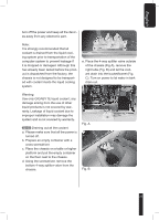
English water block are used as examples. Warning: Please make sure that the PC Power is turned off prior to installation. 4-13-1 Remove the caps and tube clips from the 4-way splitter valve. Please do not switch on the power at this moment and make sure that the valves are closed. 4-13-3 Cut a tube into suitable size, connect one side of the tube with the second splitter on the 4-way splitter valve (2) and connect the other side with the outlet of the VGA Blue Eye and fasten with tube clips. 4-13-2 Cut a tube into suitable size, connect one side of the tube with the first splitter on the 4-way splitter valve (1) and connect the other side to the inlet of the VGA Blue Eye and fasten with tube clips. 4-13-4 Cut a tube into suitable size, connect one side of the tube with the second splitter on the 4-way splitter valve (1) and connect the other side with the inlet of the chipset water block and fasten with tube clips. 21
-
 1
1 -
2
-
3
-
4
-
5
-
6
-
7
-
8
-
9
-
10
-
11
-
12
-
13
-
14
-
15
-
 16
16 -
 17
17 -
 18
18 -
 19
19 -
 20
20 -
 21
21 -
 22
22 -
 23
23 -
 24
24 -
 25
25 -
 26
26
 |
 |
