GE JV936DSS Use and Care Manual - Page 13
Determine Hood, Ductwork And Wiring Locations - model
 |
UPC - 084691003007
View all GE JV936DSS manuals
Add to My Manuals
Save this manual to your list of manuals |
Page 13 highlights
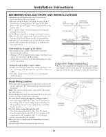
Installation Instructions DETERMINE HOOD, DUCTWORK AND WIRING LOCATIONS • Keep the wood support piece and its screws for later installation. Do not discard. • Measure desired distance from the bottom of the hood to the cooking surface, 24″ min. to 36″ Max. Refer to the previous page if the accessory duct cover will be used. • Use a level to draw a horizontal line indicating the bottom of the hood. • Use a level to draw the cooktop centerline location. • Measure 15-3/8″ up from the horizontal line for the bottom of the hood. Draw another horizontal line. • Measure 18″ up from the line for the bottom of the hood, draw another horizontal line to indicate the top of the hood. 6-7/8" Centerline To Wall 7-1/2" Dia. Hole FOR WALL VENT DUCT Top of Hood FOR CEILING VENT DUCTING Electrical Centerline 8" Min. Above Top of Hood FOR VERTICAL (Straight Up) DUCTING: • If venting out the ceiling, extend the centerline forward on the ceiling. - Measure 6-7/8″ from drywall to mark centerline for a 7-1/2″ dia. duct hole on the ceiling. - If drywall is not present, add drywall thickness to the 6-7/8″ dimension. 18" Bottom of Hood Wood Support 15-3/8" Electrical Venting through a soffit or upper cabinet. • Follow the same procedure for ceiling ducting to cut the 7-1/2″ dia. hole through the top of the cabinet or soffit. • See Step 4, page 15 for details to cut opening for duct transition. FOR DUCTING THROUGH REAR WALL: • Measure the supplied duct transition with any straight run length of duct used, plus 90° elbow height. Draw a horizontal line on the wall intersecting the centerline. House Wiring Location: • The junction box is fastened to the back of the hood on the right side. See illustrations for hood knockout locations. Note: The junction box can be relocated to the inside top of the hood. House wiring may enter the junction box from the rear or the top of the hood at the right side. To route house wiring through the ceiling or soffit: -Cut a hole approximately 1″ dia., 5-7/8″ forward on the ceiling, 11-1/8″ to the right of the centerline for 30″ models or 14-1/8 ″ to the right of the centerline for 36″ models. To route house wiring through the wall: -Cut a hole approximately 1″ dia., 10-1/16″ down from the top of the hood, 11-1/8″ to the right of the centerline for 30″ models or 14-1/8″ to the right of the centerline for 36″ models. • Remove top or rear knockout depending on your installation. • Install strain relief onto back or top of hood. Knockout Locations 14-1/8" for 36" Models 11-1/8" for 30" Models 5-7/8" 10-1/16" 14-1/8" for 36" models 11-1/8" for 30" models 13
-
 1
1 -
2
-
3
-
4
-
5
-
6
-
7
-
 8
8 -
 9
9 -
 10
10 -
 11
11 -
 12
12 -
 13
13 -
 14
14 -
 15
15 -
 16
16 -
 17
17 -
 18
18 -
19
-
20
-
21
-
22
-
23
-
24
-
25
-
26
-
27
-
28
-
29
-
30
-
31
-
32
-
33
-
34
-
35
-
36
-
37
-
38
-
39
-
40
-
41
-
42
-
43
-
44
-
45
-
46
-
47
-
48
 |
 |
