Frigidaire FHSC102WB1 Installation Instructions - Page 3
FIG.3, FIG.4, Do not use an extension cord., FIG.5
 |
View all Frigidaire FHSC102WB1 manuals
Add to My Manuals
Save this manual to your list of manuals |
Page 3 highlights
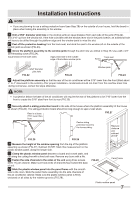
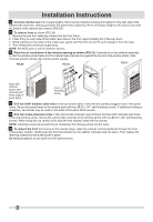
Installation Instructions 1 Make sure you have all the necessary parts. Installation kit contents (FIG.3): No. Hardware 1 Platform 2 Support brace 3 Adjustment bolt 4 Hex flange nut - 1/4 5 Track seal 6 Side channel seal 7 Window sash seal 8 Safety bracket 9 10 Qty. No. Hardware 1 11 1 12 1 13 1 14 Window locking bracket 1 15 Plastic window panel 1 16 Side channel 1 17 1 18 Panel frame/seal assembly 2 19 Support bracket (For Vinyl-Clad windows) 2 20 Safety bracket (For Vinyl-Clad windows) FIG.3 3 1 Qty. 2 62 7 1 12 1 2 17 10 4 19 1 16 1 14 1 15 NOTE: Use scale below to measure length of your screws. The scale will come in handy when separating screws for installation. IDENTIFY SCREWS BY LENGTH (13mm) (25mm) (44mm) (63mm) 18 FIG.4 9 or 10 or 11 or 17 20 8 13 17 5 7 6 (10mm) (19mm) (38mm) (50mm) 2 Choose a proper sized window, as shown (FIG.4). 15-1/2″ minimum width 16-1/4″ maximum width (for casement windows) 21-1/2″ minimum height (with window panel retainer) 20-5/16″ minimum height (window panel retainer removed) 40″ maximum height 16-1/4″ maximum width (casement windows) 15-1/2″ minimum width 21-1/2″ minimum height 40″ maximum height NOTE: Height measurement must be of a clear opening above mounting platform. In some cases, due to a variety of stop and track arrangements, the above dimensions may vary slightly. If necessary, installation can be made by alternating window jambs. (See Alternate Window Jamb Applications.) 3 Choose the proper window location. Choose a window that allows the cooled air to flow freely and directly into room(s) you wish to cool. Remember, it is difficult to move air around corners. Also, choose a window that is within 6 feet of an electrical outlet as shown (FIG.5). (See Meeting Electrical Requirements/Receptacle wiring needs.) Do not use an extension cord. FIG.5 6 feet power cord reach 3
-
 1
1 -
 2
2 -
 3
3 -
 4
4 -
 5
5 -
 6
6 -
 7
7 -
 8
8
 |
 |
