Epson ActionPC 7300 User Manual - Page 72
Changing the Jumper Settings
 |
View all Epson ActionPC 7300 manuals
Add to My Manuals
Save this manual to your list of manuals |
Page 72 highlights
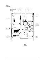
Changing the Jumper Settings The jumpers on the system board are preset to factory default positions, indicated by an asterisk (*) in the tables below. (See the illustration under "Locating the System Board Components" to locate jumpers.) Use the information in this section to change jumper settings, if necessary. Note Any jumpers not listed in the following tables are for service purposes only. Do not change their settings. Miscellaneous jumper settings Jumper number JP2 JP25 Jumper setting 1-2 * 2-3 Off* On Function L Enables on-board I/O controller Disables on-board I/O controller + Enables PCI IDE controller Disables PCI IDE controller JP49 On JP50 Off* 1-2 * 2-3 * Default setting Clears CMOS memory (resets SETUP values to factory defaults) Normal CMOS values L Enables on-board VGA controller Disables on-board VGA controller L Parallel port ECP mode DRQ jumper-settings Function DRQ1 (DACK1)* DRQ4 (DACK3) 1JP8 1 1-2 1 2-3 1JP18 I 1 2-3 I 1 1-2 I Installing and Removing Options 4-9
-
 1
1 -
2
-
3
-
4
-
5
-
6
-
7
-
8
-
9
-
10
-
11
-
12
-
13
-
14
-
15
-
16
-
17
-
18
-
19
-
20
-
21
-
22
-
23
-
24
-
25
-
26
-
27
-
28
-
29
-
30
-
31
-
32
-
33
-
34
-
35
-
36
-
37
-
38
-
39
-
40
-
41
-
42
-
43
-
44
-
45
-
46
-
47
-
48
-
49
-
50
-
51
-
52
-
53
-
54
-
55
-
56
-
57
-
58
-
59
-
60
-
61
-
62
-
63
-
64
-
65
-
66
-
 67
67 -
 68
68 -
 69
69 -
 70
70 -
 71
71 -
 72
72 -
 73
73 -
 74
74 -
 75
75 -
 76
76 -
 77
77 -
78
-
79
-
80
-
81
-
82
-
83
-
84
-
85
-
86
-
87
-
88
-
89
-
90
-
91
-
92
-
93
-
94
-
95
-
96
-
97
-
98
-
99
-
100
-
101
-
102
-
103
-
104
-
105
-
106
-
107
-
108
-
109
-
110
-
111
-
112
-
113
-
114
-
115
-
116
-
117
-
118
-
119
-
120
-
121
-
122
-
123
-
124
-
125
-
126
-
127
-
128
-
129
-
130
-
131
-
132
-
133
-
134
-
135
-
136
-
137
-
138
-
139
-
140
-
141
-
142
-
143
-
144
-
145
-
146
-
147
-
148
-
149
-
150
-
151
-
152
-
153
-
154
-
155
-
156
-
157
-
158
-
159
-
160
-
161
-
162
-
163
-
164
-
165
-
166
-
167
-
168
-
169
-
170
-
171
-
172
-
173
-
174
-
175
-
176
-
177
-
178
-
179
-
180
-
181
-
182
-
183
-
184
-
185
-
186
-
187
-
188
-
189
-
190
-
191
-
192
-
193
-
194
-
195
-
196
 |
 |
