Dell P3424WEB Curved Video Conferencing Monitor Simplified Service Manual - Page 9
No.1~4 Screw size=M3x4, Torque=5
 |
View all Dell P3424WEB manuals
Add to My Manuals
Save this manual to your list of manuals |
Page 9 highlights
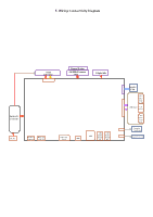
5. Disassembly and Assembly Procedures Use a Philips-head screwdriver to remove 1pcs screw for unlocking the USB board, then disconnect the USB cable and touch cable away from the S7 connectors of main board. Release the USB board away from the hook of the middle frame. (No.1 screw size=M3x3.5, Torque=4±0.5 kgfxcm) Use a Philips-head screwdriver to remove 4pcs screws for unlocking the camera module with the middle bezel, then disconnect the camera cable from S10 the connector. (No.1~2 Screw size= M3x8, Torque=4±1kgfxcm; No.3~4 Screw size= M3x4, Torque=5±1kgfxcm) 1 2 1 Use a Philips-head screwdriver to remove 6pcs screws for unlocking the two speakers away from S8 middle frame. (No.1~6 screw size=M3x6, Torque=3~5kgfxcm) 2 1 3 6 5 4 3 4 Use a Philips-head screwdriver to remove 4pcs screws for unlocking the bracket chassis with the S11 panel, then disconnect the Mic cable away from the connector of the main board. (No.1~4 Screw size=M3x4, Torque=5±1kgfxcm ) 2 3 Tear off 1pcs tape, then disconnect the speaker cable away from the board, then release the speakers from the probers of the middle frame. Disconnect the panel S9 lamp cable away from the connectors of the main board and panel, then release the panel lamp cables from the hooks of the middle frame. 4 1 Tear off 1pcs tape and disconnect the eDP cable S12 away from the connector of the panel, then lift up and take away the chassis and put it aside.
-
 1
1 -
2
-
3
-
 4
4 -
 5
5 -
 6
6 -
 7
7 -
 8
8 -
 9
9 -
 10
10 -
 11
11 -
 12
12 -
 13
13 -
 14
14 -
15
-
16
-
17
-
18
-
19
-
20
-
21
-
22
-
23
-
24
-
25
-
26
-
27
-
28
-
29
-
30
 |
 |
