Dell P2724DEB Video Conferencing Monitor Simplified Service Manual - Page 14
No.1~4 Screw size= M3x8, Torque=6, 5kgfxcm, No.1~4 Screw size= M3x4, Torque=5, 1kgfxcm, No.1~2screw
 |
View all Dell P2724DEB manuals
Add to My Manuals
Save this manual to your list of manuals |
Page 14 highlights
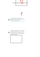
5. Disassembly and Assembly Procedures Use a Philips-head screwdriver to tighten 4pcs screws for locking the camera unit with the middle S14 frame. (No.1~4 Screw size= M3x8, Torque=6±0.5kgfxcm) Take 1pcs camera unit assembled in LCM line, then S11 locate the camera unit into the pins of the middle frame. 3 4 1 2 Use a Philips-head screwdriver to tighten 2pcs screws for locking the middle frame with panel S15 module and front bezel. (No.1~2screw size=M2x3.3,Torque=1±0.2kgfxcm) Move the bracket and put it on the back of panel, S12 then connect the 2pcs LVDS cables to the connectors of the panel module. 2 1 Take 1pcs USB board, 2pcs connective cables and 1pcs conductive foam. Connect the 2pcs cables to S16 the connectors of the USB board, then turn over the board and paste the conductive foam on the back of the USB board as the picture below shown. Use a Philips-head screwdriver to tighten 4pcs screws for locking the bracket with the panel, then take 1pcs S13 camera cable to connect camera with main board. (No.1~4 Screw size= M3x4, Torque=5±1kgfxcm ) 2 3 4 1
-
 1
1 -
2
-
3
-
4
-
5
-
6
-
7
-
8
-
 9
9 -
 10
10 -
 11
11 -
 12
12 -
 13
13 -
 14
14 -
 15
15 -
 16
16 -
 17
17 -
 18
18 -
 19
19 -
20
-
21
-
22
-
23
-
24
-
25
-
26
-
27
-
28
-
29
-
30
-
31
-
32
 |
 |
