Dell P2425HE Monitor Simplified Service Manual - Page 12
Control board from Rear Cover, Unplug Backlight wire from LED
 |
View all Dell P2425HE manuals
Add to My Manuals
Save this manual to your list of manuals |
Page 12 highlights
S6 Unlock 3 screws to disassemble "Control board" from "Rear Cover" Tear off "Control board FFC" from "Rear Cover" and take off "Control board" from "Rear Cover" S8 Tear off 2 tapes from "Backlight wire" Unplug "Backlight wire" from "LED Driver board" and "Panel" (Screw Torque: 1.6-1.8 kgf) S7 Disassemble "Control board FFC" from "Control board" S9 Tear off a black tape from "USB board FFC" and "Panel Disassemble "USB board FFC" from "USB board" and "Interface board" Unlock 1 screw on "USB board" Disassemble "USB board" from "Middle Frame" (Screw Torque: 4.5±0.5 kgf) - 12 -
-
 1
1 -
2
-
3
-
4
-
5
-
6
-
 7
7 -
 8
8 -
 9
9 -
 10
10 -
 11
11 -
 12
12 -
 13
13 -
 14
14 -
 15
15 -
 16
16 -
 17
17 -
18
-
19
-
20
-
21
-
22
-
23
-
24
-
25
-
26
-
27
-
28
-
29
 |
 |
- 12 -
S6
Unlock 3 screws to disassemble
“Control board” from “Rear Cover”
Tear off “Control board FFC” from
“Rear Cover” and take off “Control
board” from “Rear Cover”
(Screw Torque: 1.6-1.8 kgf)
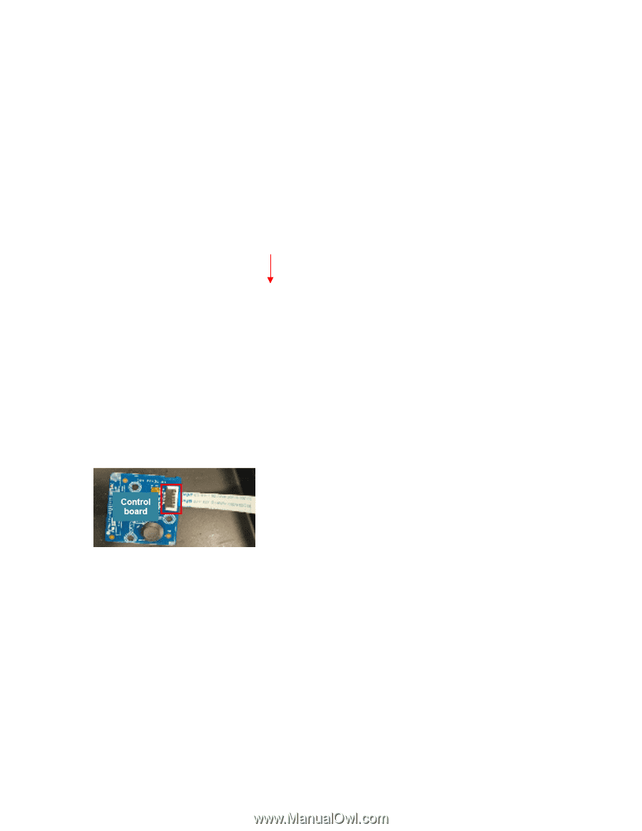
S7
Disassemble “Control board FFC” from
“Control board”
S8
Tear off 2 tapes from “Backlight wire”
Unplug “Backlight wire” from “LED
Driver board” and “Panel”
S9
Tear off a black tape from “USB board
FFC” and “Panel
Disassemble “USB board FFC” from
“USB board” and “Interface board”
Unlock 1 screw on “USB board”
Disassemble “USB board” from “Middle
Frame”
(Screw Torque: 4.5±0.5 kgf)