Dell Inspiron 5490 Service Manual
Dell Inspiron 5490 Manual
 |
View all Dell Inspiron 5490 manuals
Add to My Manuals
Save this manual to your list of manuals |
Dell Inspiron 5490 manual content summary:
- Dell Inspiron 5490 | Service Manual - Page 1
Inspiron 5490 Service Manual Regulatory Model: P116G Regulatory Type: P116G001 - Dell Inspiron 5490 | Service Manual - Page 2
of data and tells you how to avoid the problem. WARNING: A WARNING indicates a potential for property damage, personal injury, or death. © 2019 Dell Inc. or its subsidiaries. All rights reserved. Dell, EMC, and other trademarks are trademarks of Dell Inc. or its subsidiaries. Other trademarks may be - Dell Inspiron 5490 | Service Manual - Page 3
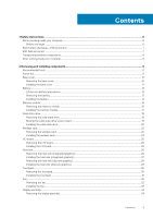
Contents 1 Safety instructions...6 Before working inside your computer...6 Before you begin ...6 Electrostatic discharge-ESD protection...7 ESD field service kit ...7 Transporting sensitive components...8 After working inside your computer...8 2 Removing and installing components 9 Recommended - Dell Inspiron 5490 | Service Manual - Page 4
or changing an existing system setup password 65 Clearing CMOS settings...66 Clearing BIOS (System Setup) and System passwords 66 5 Troubleshooting...67 Enhanced Pre-Boot System Assessment (ePSA) diagnostics 67 Running the ePSA diagnostics...67 System diagnostic lights...67 Recovering the - Dell Inspiron 5490 | Service Manual - Page 5
Flashing the BIOS...69 WiFi power cycle...69 Flea power release...69 6 Getting help and contacting Dell 71 Contents 5 - Dell Inspiron 5490 | Service Manual - Page 6
, not by its pins. CAUTION: You should only perform troubleshooting and repairs as authorized or directed by the Dell technical assistance team. Damage due to servicing that is not authorized by Dell is not covered by your warranty. See the safety instructions that shipped with the product or at www - Dell Inspiron 5490 | Service Manual - Page 7
shut-down instructions. 3. Disconnect such as intermittent problems or a shortened Dell products, the sensitivity to static damage is now higher than in previous Dell damage to recognize and troubleshoot is the intermittent (also known as bonding. Use only Field Service kits with a wrist strap, mat, - Dell Inspiron 5490 | Service Manual - Page 8
service technicians use the traditional wired ESD grounding wrist strap and protective anti-static mat at all times when servicing Dell base, and point your toes out. 2. Tighten stomach muscles. Abdominal muscles support your spine when you lift, offsetting the force of the load. 3. Lift instructions - Dell Inspiron 5490 | Service Manual - Page 9
2 Removing and installing components Recommended tools The procedures in this document may require the following tools: • Phillips screwdriver #1 • Plastic scribe Screw list NOTE: When removing screws from a component, it is recommended to note the screw type, the quantity of screws, and then - Dell Inspiron 5490 | Service Manual - Page 10
Component Wireless-card bracket Secured to System board Power-button board/ Fingerprint-reader board bracket Power-button board/ Fingerprint-reader board Palm-rest and keyboard assembly Palm-rest and keyboard assembly Base cover Screw type M2x3 M2x2 M2x3 Quantity 1 2 2 Screw image Removing - Dell Inspiron 5490 | Service Manual - Page 11
Steps 1. Loosen the two captive screws and remove the seven screws (M2x5) that secure the base cover to the palm-rest and keyboard assembly. 2. Pry the base cover starting from the right hinge and work your way around. 3. Lift the base cover off the palm-rest and keyboard assembly. 4. Peel off the - Dell Inspiron 5490 | Service Manual - Page 12
12 Removing and installing components - Dell Inspiron 5490 | Service Manual - Page 13
battery. • Ensure any screws during the servicing of this product are not lost or , contact for assistance and further instructions. • If the battery gets Dell technical support for assistance. See www.dell.com/contactdell. • Always purchase genuine batteries from www.dell.com or authorized Dell - Dell Inspiron 5490 | Service Manual - Page 14
Steps 1. Peel off the tape that secures the battery cable to the system board. 2. Disconnect the battery cable from the system board. 3. Remove the two screws (M2x3) that secure the battery to the palm-rest and keyboard assembly. 4. Slide the tabs on the battery out of the slots on the palm-rest and - Dell Inspiron 5490 | Service Manual - Page 15
Steps 1. Align the four tabs on the battery into the slots on the palm-rest and keyboard assembly and insert the battery into place. 2. Align the screw holes on the battery with the screw holes on the palm-rest and keyboard assembly and place the battery on the palm- rest and keyboard assembly. 3. - Dell Inspiron 5490 | Service Manual - Page 16
Memory module Removing the memory module Prerequisites NOTE: The primary memory module is integrated into the system board. This procedure is for removing the secondary memory module. 1. Follow the procedure in Before working inside your computer. 2. Remove the base cover. 3. Remove the battery. - Dell Inspiron 5490 | Service Manual - Page 17
2. With the memory module visible, use your fingertips to spread apart the securing clips on the memory-module slot until the memory module pops up. 3. Slide and remove the memory module from the memory-module slot. Installing the memory module Prerequisites If you are replacing a component, remove - Dell Inspiron 5490 | Service Manual - Page 18
Next steps 1. Install the battery. 2. Install the base cover. 3. Follow the procedure in After working inside your computer. Solid-state drive Removing the solid-state drive Prerequisites 1. Follow the procedure in Before working inside your computer. 2. Remove the base cover. 3. Remove the battery. - Dell Inspiron 5490 | Service Manual - Page 19
M.2 2280 solid-state drive Steps 1. Remove the screw (M2x3) that secures the solid-state drive to the system board. 2. Slide and remove the solid-state drive from the solid-state drive slot on the system board. Moving the solid-state drive screw mount Prerequisites 1. Follow the procedure in Before - Dell Inspiron 5490 | Service Manual - Page 20
About this task The following image indicates the location of the solid-state drive screw mount and provides a visual representation of the procedure to move the screw mount to another location that accommodates the form factor. Steps 1. Slide the screw mount out of the screw-mount slot on the palm - Dell Inspiron 5490 | Service Manual - Page 21
M.2 2242 solid-state drive M.2 2280 solid-state drive Removing and installing components 21 - Dell Inspiron 5490 | Service Manual - Page 22
Steps 1. Align the notch on the solid-state drive with the tab on the solid-state drive slot. 2. Slide the solid-state drive into the solid-state slot on the system board. 3. Replace the screw (M2x3) that secures the solid-state drive to the system board. Next steps 1. Install the battery. 2. - Dell Inspiron 5490 | Service Manual - Page 23
Steps 1. Remove the screw (M2x3) that secures the wireless-card bracket to the wireless card. 2. Remove the wireless-card bracket off the wireless card. 3. Disconnect the antenna cables from the wireless card. 4. Slide and remove the wireless card from the wireless-card slot. Installing the wireless - Dell Inspiron 5490 | Service Manual - Page 24
slot. 2. Connect the antenna cables to the wireless card. The following table provides the antenna-cable color scheme for the wireless card supported by your computer. Table 2. Antenna-cable color scheme Connectors on the wireless card Antenna-cable color Main (white triangle) White Auxiliary - Dell Inspiron 5490 | Service Manual - Page 25
off the I/O-board cable connector. 2. Open the latch and disconnect the I/O-board cable from the I/O board. 3. Remove the I/O-board cable from the routing guides on the fan. 4. Remove the two screws (M2x3) that secure the I/O board to the palm-rest and keyboard assembly. 5. Lift the I/O board off - Dell Inspiron 5490 | Service Manual - Page 26
Steps 1. Using the alignment posts, place the I/O board on the palm-rest and keyboard assembly. 2. Route the I/O-board cable through the routing guides on the fan. 3. Replace the two screws (M2x3) that secure the I/O board to the palm-rest and keyboard assembly. 4. Connect the I/O-board cable to the - Dell Inspiron 5490 | Service Manual - Page 27
Steps 1. In reverse-sequential order (as indicated on the heat sink), loosen the four captive screws that secure the heat sink to the system board. 2. Lift the heat sink off the system board. Installing the heat sink (integrated graphics) Prerequisites If you are replacing a component, remove the - Dell Inspiron 5490 | Service Manual - Page 28
Steps 1. Align the screw holes on the heat sink with the screw holes on the system board. 2. In sequential order (indicated on the heat sink), tighten the four captive screws that secure the heat sink to the system board. Next steps 1. Install the battery. 2. Install the base cover. 3. Follow the - Dell Inspiron 5490 | Service Manual - Page 29
Steps 1. In reverse-sequential order (as indicated on the heat sink), loosen the seven captive screws that secure the heat sink to the system board. 2. Lift the heat sink off the system board. Installing the heat sink (discrete graphics) Prerequisites If you are replacing a component, remove the - Dell Inspiron 5490 | Service Manual - Page 30
Steps 1. Align the screw holes on the heat sink with the screw holes on the system board. 2. In sequential order (indicated on the heat sink), tighten the seven captive screws that secure the heat sink to the system board. Next steps 1. Install the battery. 2. Install the base cover. 3. Follow the - Dell Inspiron 5490 | Service Manual - Page 31
Steps 1. Peel the tapes that secure the antenna cables to the palm-rest and keyboard assembly. 2. Open the latch and disconnect the touchpad cable from the system board. 3. Gently slide the touchpad-cable connector under the antenna cables so that the touchpad cable is over the antenna cables. 4. - Dell Inspiron 5490 | Service Manual - Page 32
Steps 1. Align and place the touchpad into the slot on the palm-rest and keyboard assembly. 2. Replace the four screws that (M2x2) secure the touchpad to the palm-rest and keyboard assembly. 3. Align and place the touchpad bracket into the slot on the palm-rest and keyboard assembly. 4. Replace the - Dell Inspiron 5490 | Service Manual - Page 33
off the I/O-board cable connector. 2. Lift the latch and disconnect the I/O-board cable from the I/O board. 3. Remove the I/O-board cable from the routing guides on the fan. 4. Remove the two screws (M2x3) that secure the fan to the system board. 5. Disconnect the fan cable from the system board - Dell Inspiron 5490 | Service Manual - Page 34
palm-rest and keyboard assembly. 4. Connect the I/O-board cable to the system board and I/O board. 5. Route the I/O-board cable through the routing guides on the fan. 6. Reconnect the I/O-board cable to the I/O board and close the latch. 7. Adhere the tape that secures the I/O-board cable connector - Dell Inspiron 5490 | Service Manual - Page 35
Steps 1. Peel the tape that secures the display-cable connector to the system board. 2. Open the latch and disconnect the display cable from the system board. 3. Remove the four screws (M2.5x5) that secure the left and the right display hinges to the palm-rest and keyboard assembly. Removing and - Dell Inspiron 5490 | Service Manual - Page 36
4. Open the display hinges at an angle of 90 degrees. 5. Gently slide and lift the palm-rest and keyboard assembly off the display assembly. Installing the display assembly Prerequisites If you are replacing a component, remove the existing component before performing the installation procedure. - Dell Inspiron 5490 | Service Manual - Page 37
Removing and installing components 37 - Dell Inspiron 5490 | Service Manual - Page 38
38 Removing and installing components - Dell Inspiron 5490 | Service Manual - Page 39
Steps 1. Place the display assembly on a clean and flat surface. 2. Align and place the palm-rest and keyboard assembly on the display assembly. 3. Using the alignment posts, close the left and the right display hinges. 4. Replace the four screws (M2.5x5) that secure the left and the right display - Dell Inspiron 5490 | Service Manual - Page 40
cable to the palm-rest and keyboard assembly. 3. Connect the coin-cell battery cable to the system board. 4. Route the speaker cable through the routing guides on the system board. 5. Adhere the tape that secures the speaker cable to the system board. 6. Connect the speaker cable to the system board - Dell Inspiron 5490 | Service Manual - Page 41
off the tape that secures the speaker cable to the system board. 3. Note the speaker-cable routing and remove the cable from the routing guides. 4. Lift the speakers, along with the speaker cable, off the palm-rest and keyboard assembly. Installing the speakers Prerequisites If you are replacing - Dell Inspiron 5490 | Service Manual - Page 42
Steps 1. Using the alignment posts, place the speakers on the palm-rest and keyboard assembly. 2. Route the speaker cables through the routing guides on the palm-rest and keyboard assembly. 3. Adhere the tape that secures the speaker cable to the system board. 4. Connect the speaker cable to the - Dell Inspiron 5490 | Service Manual - Page 43
Steps 1. Disconnect the power-adapter port cable from the system board. 2. Remove the screw (M2x3) that secures the power-adapter port to the palm-rest and keyboard assembly. 3. Lift the power-adapter port, along with its cable, off the palm-rest and keyboard assembly. Installing the power-adapter - Dell Inspiron 5490 | Service Manual - Page 44
Steps 1. Place the power-adapter port into the slot on the palm-rest and keyboard assembly. 2. Replace the screw (M2x3) that secures the power-adapter port to the palm-rest and keyboard assembly. 3. Connect the power-adapter cable to the connector on the system board. Next steps 1. Install the - Dell Inspiron 5490 | Service Manual - Page 45
Steps 1. Remove the two screws (M2.5x5) that secure the right display hinge to the palm-rest and keyboard assembly. 2. Lift the right display hinge. 3. Lift the latch and disconnect the power-button cable from the system board. 4. Peel the adhesive tape above the power-button board. 5. Remove the - Dell Inspiron 5490 | Service Manual - Page 46
Steps 1. Align and place the power-button board into the slot on the palm-rest and keyboard assembly. 2. Replace the two screws (M2x2) and the two screws (M2x3) that secure the power-button board to the palm-rest and keyboard assembly. 3. Adhere the adhesive tape above the power-button board. 4. - Dell Inspiron 5490 | Service Manual - Page 47
Power button with fingerprint reader (optional) Removing the power button with fingerprint reader (optional) Prerequisites NOTE: This procedure is only applicable to computers shipped with a power button with fingerprint reader. 1. Follow the procedure in Before working inside your computer. 2. - Dell Inspiron 5490 | Service Manual - Page 48
Steps 1. Remove the two screws (M2.5x5) that secure the right display hinge to the palm-rest and keyboard assembly. 2. Lift the right display hinge. 3. Open the latch and disconnect the power-button cable from the connector on the system board. 4. Disconnect the fingerprint-reader cable from the - Dell Inspiron 5490 | Service Manual - Page 49
Steps 1. Align and place the power button with fingerprint reader into the slot on the palm-rest and keyboard assembly. 2. Replace the two screws (M2x3) that secure the power button with fingerprint reader to the palm-rest and keyboard assembly. 3. Replace the two screws (M2x2) that secure the power - Dell Inspiron 5490 | Service Manual - Page 50
System board Removing the system board Prerequisites NOTE: The system board is removed and installed with the heat sink attached, when replacing the palm-rest and keyboard assembly. This simplifies the procedure and avoids breaking the thermal bond between system board and the heat sink. 1. Follow - Dell Inspiron 5490 | Service Manual - Page 51
Steps 1. Open the latch and disconnect the I/O-board cable from the system board. 2. Open the latch and disconnect the power-adapter port cable from the system board. 3. Disconnect the coin-cell battery cable and the speaker cable from the system board. Removing and installing components 51 - Dell Inspiron 5490 | Service Manual - Page 52
4. Open the respective latches and disconnect the touchpad cable, the keyboard-backlight cable, and the keyboard cable from their connectors on the system board. 5. Remove the five screws (M2x2) and the two screws (M2x3) that secure the system board to the palm-rest and keyboard assembly. 6. Lift - Dell Inspiron 5490 | Service Manual - Page 53
4. Connect the coin-cell battery cable and the speaker cable to the connectors on the system board. 5. Connect the power-adapter port cable to the system board and close the latch. 6. Connect the I/O-board cable to the system board and close the latch. Next steps 1. Install the display assembly. 2. - Dell Inspiron 5490 | Service Manual - Page 54
Installing the palm-rest and keyboard assembly Prerequisites If you are replacing a component, remove the existing component before performing the installation procedure. About this task Place the palm-rest and keyboard assembly on a flat surface. Next steps 1. Install the system board. NOTE: The - Dell Inspiron 5490 | Service Manual - Page 55
Intel Serial IO driver In the Device Manager, check if the Intel Serial IO driver is installed. Install the driver updates from www.dell.com/support. Intel Trusted Execution Engine Interface In the Device Manager, check if the Intel Trusted Execution Engine Interface driver is installed. Install the - Dell Inspiron 5490 | Service Manual - Page 56
. Use the BIOS Setup program for the following purposes: • Get information about the hardware installed in your computer, such as the amount of RAM and the size of the hard drive. • Change the system configuration information. • Set or change a user-selectable option, such as the user password - Dell Inspiron 5490 | Service Manual - Page 57
drive or hard drive). During the Power-on Self Test (POST), when the Dell logo appears, you can: • Access System Setup by pressing F2 key • Bring System information menu Overview Inspiron 5490 BIOS Version Displays the BIOS version number. Service Tag Displays the Service Tag of the computer. - Dell Inspiron 5490 | Service Manual - Page 58
Overview Processor L2 Cache Processor L3 Cache Microcode Version Intel Hyper-Threading Capable 64-Bit Technology MEMORY Memory Installed Memory Available Memory Speed Memory Channel Mode Memory Technology DIMM_SLOT 1 DIMM_SLOT 2 DEVICES Panel Type Video Controller Video Memory Wi-Fi Device Native - Dell Inspiron 5490 | Service Manual - Page 59
mode of the integrated SATA hard drive controller (only for computers shipped with hard drive). Default: RAID. SATA is configured to support RAID (Intel Rapid Restore Technology). Drive Information Enable SMART Reporting Displays the information of various onboard drives. Enables or disables SMART - Dell Inspiron 5490 | Service Manual - Page 60
UEFI capsule update packages. Enables, disables, or permanently disables the BIOS module interface of the optional Absolute Persistence Module service from Absolute Software. Default: Enable Absolute SMM Security Mitigation Enables or disables additional UEFI SMM Security Mitigation protections - Dell Inspiron 5490 | Service Manual - Page 61
Mode Key Management Selects the custom values for expert key management. Default: PK Table 10. System setup options-Performance menu Performance Multi-Core Support Active Cores Changes the number of CPU cores available to the operating system. The default value is set to the maximum number of - Dell Inspiron 5490 | Service Manual - Page 62
Power Management Enable USB Wake Support Wake on Dell USB-C Dock Auto On Time Block Sleep Battery Standby mode. Default: OFF Enables the computer to wake from Standby when it is connected to a Dell USB-C dock. Default: ON Enables the computer to automatically power on for defined days and times. - Dell Inspiron 5490 | Service Manual - Page 63
Tag that can be used by an IT administrator to uniquely identify a particular system. Once set in BIOS, the Asset Tag cannot be changed. Service Tag Displays the Service Tag of the computer. BIOS Recovery from Hard Drive Enables the computer to recover from a bad BIOS image, as long as the Boot - Dell Inspiron 5490 | Service Manual - Page 64
automatic boot flow for SupportAssist System Resolution Console and for Dell operating system Recovery tool. Default: 2 SupportAssist OS Recovery system errors. Default: ON BIOSConnect Enables or disables attempting cloud Service OS recovery. Default: ON System and setup password Table 18. - Dell Inspiron 5490 | Service Manual - Page 65
NOTE: System and setup password feature is disabled. Assigning a system setup password Prerequisites You can assign a new System or Admin Password only when the status is in Not Set. About this task To enter the system setup, press F2 immediately after a power-on or re-boot. Steps 1. In the System - Dell Inspiron 5490 | Service Manual - Page 66
. Clearing BIOS (System Setup) and System passwords About this task To clear the system or BIOS passwords, contact Dell technical support as described at www.dell.com/contactdell. NOTE: For information on how to reset Windows or application passwords, refer to the documentation accompanying Windows - Dell Inspiron 5490 | Service Manual - Page 67
successfully • View error messages that inform you of problems encountered during testing NOTE: Some tests for specific are displayed. Note the error code and validation number and contact Dell. System diagnostic lights Battery-status light Indicates the power and battery . Troubleshooting 67 - Dell Inspiron 5490 | Service Manual - Page 68
website to troubleshoot and fix your computer when it fails to boot into their primary operating system due to software or hardware failures. For more information about the Dell SupportAssist OS Recovery, see Dell SupportAssist OS Recovery User's Guide at www.dell.com/ support. Flashing BIOS - Dell Inspiron 5490 | Service Manual - Page 69
dell.com/support. 3. Click Product support, enter the Service Tag of your computer, and then click Submit. NOTE: If you do not have the Service Tag, use the auto-detect feature or manually update file icon and follow the instructions on the screen. WiFi power provides the instructions on how to - Dell Inspiron 5490 | Service Manual - Page 70
3. Press and hold the power button for 15 seconds to drain the flea power. 4. Connect the power adapter to your computer. 5. Turn on your computer. 70 Troubleshooting - Dell Inspiron 5490 | Service Manual - Page 71
varies by country. Contact Support NOTE: Availability varies by country. Online help for operating system Troubleshooting information, user manuals, setup instructions, product specifications, technical help blogs, drivers, software updates, and so on. Dell knowledge base articles for a variety
-
 1
1 -
 2
2 -
 3
3 -
 4
4 -
 5
5 -
 6
6 -
 7
7 -
8
-
9
-
10
-
11
-
12
-
13
-
14
-
15
-
16
-
17
-
18
-
19
-
20
-
21
-
22
-
23
-
24
-
25
-
26
-
27
-
28
-
29
-
30
-
31
-
32
-
33
-
34
-
35
-
36
-
37
-
38
-
39
-
40
-
41
-
42
-
43
-
44
-
45
-
46
-
47
-
48
-
49
-
50
-
51
-
52
-
53
-
54
-
55
-
56
-
57
-
58
-
59
-
60
-
61
-
62
-
63
-
64
-
65
-
66
-
67
-
68
-
69
-
70
-
71
 |
 |

Inspiron 5490
Service Manual
Regulatory Model: P116G
Regulatory Type: P116G001