Dell Inspiron 24 5430 All-in-One Owners Manual - Page 81
Installing the system board
 |
View all Dell Inspiron 24 5430 All-in-One manuals
Add to My Manuals
Save this manual to your list of manuals |
Page 81 highlights
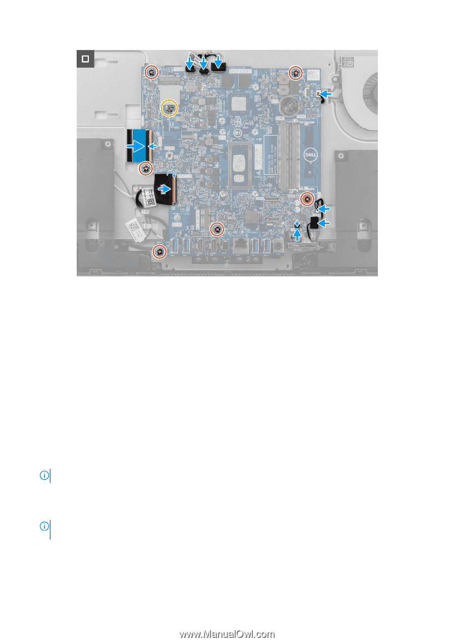
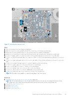
Figure 55. Installing the system board Steps 1. Place the system board on the display-assembly base. 2. Align the screw holes on the system board with the screw holes on the display-assembly base. 3. Replace the six screws (M3x5) that secure the system board to the display-assembly base. 4. Replace the solid-state drive screw mount (M3x4) that secures the system board to the display-assembly base. 5. Connect the display cable to its connector (LVDS) on the system board and close the latch to secure the cable. 6. Connect the power-button board cable to its connector (TYPE-C) on the system board and close the latch to secure the cable. 7. Connect the media-card reader cable to its connector (SD CARD) on the system board and close the latch to secure the cable. 8. Connect the microphone-module cable to its connector (DMIC1) on the system board. 9. Connect the speaker cable to its connector (SPK1) on the system board. 10. Connect the fan cable to its connector (FAN1) on the system board. 11. Connect the backlight cable to its connector (BL) on the system board. 12. Connect the camera cable to its connector (WEBCAM) on the system board. 13. Connect the touchscreen cable to its connector (TOUCH) on the system board. NOTE: This cable is only available on computers that support the touch option. Next steps 1. Install the integrated heat sink or, discrete heat sink, as applicable. NOTE: The system board can be removed and installed along with the heat sink. This simplifies the removal and installation procedure and avoids breaking the thermal bond between the system board and heat sink. 2. Install the M.2 2230 solid-state drive. 3. Install the wireless card. 4. Install the memory module. 5. Install the system-board shield. Removing and installing Field Replaceable Units (FRUs) 81
-
 1
1 -
2
-
3
-
4
-
5
-
6
-
7
-
8
-
9
-
10
-
11
-
12
-
13
-
14
-
15
-
16
-
17
-
18
-
19
-
20
-
21
-
22
-
23
-
24
-
25
-
26
-
27
-
28
-
29
-
30
-
31
-
32
-
33
-
34
-
35
-
36
-
37
-
38
-
39
-
40
-
41
-
42
-
43
-
44
-
45
-
46
-
47
-
48
-
49
-
50
-
51
-
52
-
53
-
54
-
55
-
56
-
57
-
58
-
59
-
60
-
61
-
62
-
63
-
64
-
65
-
66
-
67
-
68
-
69
-
70
-
71
-
72
-
73
-
74
-
75
-
 76
76 -
 77
77 -
 78
78 -
 79
79 -
 80
80 -
 81
81 -
 82
82 -
 83
83 -
 84
84 -
 85
85 -
 86
86 -
87
-
88
-
89
-
90
-
91
-
92
-
93
-
94
-
95
-
96
-
97
-
98
-
99
-
100
-
101
-
102
-
103
-
104
-
105
-
106
-
107
-
108
-
109
-
110
-
111
-
112
-
113
-
114
-
115
 |
 |