Dell Inspiron 16 7640 2-in-1 Owners Manual - Page 74
Prerequisites, About this task, System-board connectors
 |
View all Dell Inspiron 16 7640 2-in-1 manuals
Add to My Manuals
Save this manual to your list of manuals |
Page 74 highlights
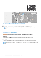
Prerequisites 1. Follow the procedure in Before working inside your computer. NOTE: Ensure that your computer is in Service Mode. For more information, see step 6 in Before working inside your computer. 2. Remove the base cover. 3. Remove the 4-cell battery (64 Wh) or the 6-cell battery (90 Wh), whichever is applicable. 4. Remove the M.2 2230 solid-state drive or the M.2 2280 solid-state drive, whichever is applicable. 5. Remove the wireless card. 6. Remove the fan. 7. Remove the heat sink. About this task The following image indicates the connectors on your system board. Figure 49. System-board connectors 1. Fan-cable connector 2. Display-board cable connector 3. Display-cable connector 4. M.2 solid-state drive connector 5. Battery-cable connector 6. Keyboard-backlight cable connector 7. Display-speaker cable connector 74 Removing and installing Field Replaceable Units (FRUs)
-
 1
1 -
2
-
3
-
4
-
5
-
6
-
7
-
8
-
9
-
10
-
11
-
12
-
13
-
14
-
15
-
16
-
17
-
18
-
19
-
20
-
21
-
22
-
23
-
24
-
25
-
26
-
27
-
28
-
29
-
30
-
31
-
32
-
33
-
34
-
35
-
36
-
37
-
38
-
39
-
40
-
41
-
42
-
43
-
44
-
45
-
46
-
47
-
48
-
49
-
50
-
51
-
52
-
53
-
54
-
55
-
56
-
57
-
58
-
59
-
60
-
61
-
62
-
63
-
64
-
65
-
66
-
67
-
68
-
 69
69 -
 70
70 -
 71
71 -
 72
72 -
 73
73 -
 74
74 -
 75
75 -
 76
76 -
 77
77 -
 78
78 -
 79
79 -
80
-
81
-
82
-
83
-
84
-
85
-
86
-
87
-
88
-
89
-
90
-
91
-
92
-
93
-
94
-
95
-
96
-
97
-
98
-
99
-
100
-
101
-
102
-
103
-
104
-
105
-
106
-
107
-
108
 |
 |
