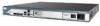
Cisco 2811 Hardware Guide - Page 28
Cisco 2811 Chassis
 |
UPC - 882658101816
View all Cisco 2811 manuals
Add to My Manuals
Save this manual to your list of manuals |
Page 28 highlights
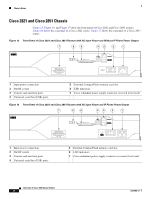
95551 Chassis Views Cisco 2811 Chassis Figure 9, Figure 10, and Figure 11 show the front panel of a Cisco 2811 router. Figure 12 shows the rear panel of a Cisco 2811 router. Figure 9 Front Panel of Cisco 2811 Router with AC Input Power and Without IP Phone Power Output 7 6 54 3 2 1 SYS AUX/ SYS 1 PWR PWR ACT CF COMPACT FLASH 0 Do Not Remove During Network Operation CONSOLE AUX OPTIONAL RPS INPUT 12V 11A 100-240 V~ 2A 50/60 Hz 1 Input power connection 2 On/Off switch 3 Cisco redundant power supply connector (covered if not used) 4 Console and auxiliary ports 5 Universal serial bus (USB) ports 6 External CompactFlash memory card slot 7 LED indicators Figure 10 Front Panel of Cisco 2811 Router with AC Input Power and with IP Phone Power Output 7 6 54 3 2 1 SYS AUX/ SYS 1 PWR PWR ACT CF COMPACT FLASH 0 Do Not Remove During Network Operation CONSOLE AUX OPTIONAL RPS INPUT 12V 11A -48V 4A 100-240V~ 8A 50/60 Hz 95550 1 Input power connection 5 Universal serial bus (USB) ports 2 On/Off switch 6 External CompactFlash memory card slot 3 Cisco redundant power supply connector (covered if not used) 7 LED indicators 4 Console and auxiliary ports Overview of Cisco 2800 Series Routers 12 OL-5783-01
-
 1
1 -
2
-
3
-
4
-
5
-
6
-
7
-
8
-
9
-
10
-
11
-
12
-
13
-
14
-
15
-
16
-
17
-
18
-
19
-
20
-
21
-
22
-
 23
23 -
 24
24 -
 25
25 -
 26
26 -
 27
27 -
 28
28 -
 29
29 -
 30
30 -
 31
31 -
 32
32 -
 33
33 -
34
-
35
-
36
-
37
-
38
-
39
-
40
-
41
-
42
-
43
-
44
-
45
-
46
-
47
-
48
-
49
-
50
-
51
-
52
-
53
-
54
-
55
-
56
-
57
-
58
-
59
-
60
-
61
-
62
-
63
-
64
-
65
-
66
-
67
-
68
-
69
-
70
-
71
-
72
-
73
-
74
-
75
-
76
-
77
-
78
-
79
-
80
-
81
-
82
-
83
-
84
-
85
-
86
-
87
-
88
-
89
-
90
-
91
-
92
-
93
-
94
-
95
-
96
-
97
-
98
-
99
-
100
-
101
-
102
-
103
-
104
-
105
-
106
-
107
-
108
-
109
-
110
-
111
-
112
-
113
-
114
-
115
-
116
-
117
-
118
-
119
-
120
-
121
-
122
-
123
-
124
-
125
-
126
-
127
-
128
-
129
-
130
-
131
-
132
-
133
-
134
-
135
-
136
-
137
-
138
-
139
-
140
-
141
-
142
-
143
-
144
-
145
-
146
-
147
-
148
-
149
-
150
-
151
-
152
-
153
-
154
-
155
-
156
-
157
-
158
-
159
-
160
-
161
-
162
-
163
-
164
-
165
-
166
-
167
-
168
-
169
-
170
-
171
-
172
-
173
-
174
-
175
-
176
-
177
-
178
-
179
-
180
-
181
-
182
-
183
-
184
-
185
-
186
 |
 |
