Canon LX-MU800Z User Manual - Page 92
Distance from Ceiling to Lens Center (ℓ), Ceiling-mount Bracket, Assembly and Installation
 |
View all Canon LX-MU800Z manuals
Add to My Manuals
Save this manual to your list of manuals |
Page 92 highlights
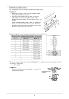
Distance from Ceiling to Lens Center (ℓ) RS-CL15 24.6 cm / 0.8' When RS-CL08 is used 59.6 cm / 2.0' to 79.6 cm / 2.6' When RS-CL09 is used 79.6 cm / 2.6' to 119.6 cm / 3.9' For more detailed information on the screen sizes and the projection distance, see "Relationship Between Image Size and Projecting Distance" on page 96. Ceiling-mount Bracket 100 mm 100 mm / 3.9" / 3.9" / 3.9" 100 mm 100 mm 80 mm 80 mm / 3.1" / 3.1" / 3.9" 80 mm 80 mm / 3.1" / 3.1" Assembly and Installation Installation to Flat and Level Ceiling Preparation: Remove four M5 screws to separate joint fitting from the ceiling-mount bracket. Direction to the screen 1. Make a hole in the ceiling to install the ceiling-mount bracket and cables. Caution: ■■ Mounting position varies on the projector used. Make sure that the template sheet (A) corresponding to the projector is used. ■■ When determining the hole position, use the supplied template sheet (A). ■■ The direction to the screen is indicated on the template sheet (A). 2. Use four M13 screws, to secure the ceiling-mount bracket to the ceiling with the arrow facing toward the screen. ■■ Before securing the ceiling-mount bracket, be sure to remove the template sheet (A). ■■ The M13 screws are not included in the supplied parts. Prepare the M13 screws suitable for the ceiling structure. Direction to the screen 86
-
 1
1 -
2
-
3
-
4
-
5
-
6
-
7
-
8
-
9
-
10
-
11
-
12
-
13
-
14
-
15
-
16
-
17
-
18
-
19
-
20
-
21
-
22
-
23
-
24
-
25
-
26
-
27
-
28
-
29
-
30
-
31
-
32
-
33
-
34
-
35
-
36
-
37
-
38
-
39
-
40
-
41
-
42
-
43
-
44
-
45
-
46
-
47
-
48
-
49
-
50
-
51
-
52
-
53
-
54
-
55
-
56
-
57
-
58
-
59
-
60
-
61
-
62
-
63
-
64
-
65
-
66
-
67
-
68
-
69
-
70
-
71
-
72
-
73
-
74
-
75
-
76
-
77
-
78
-
79
-
80
-
81
-
82
-
83
-
84
-
85
-
86
-
 87
87 -
 88
88 -
 89
89 -
 90
90 -
 91
91 -
 92
92 -
 93
93 -
 94
94 -
 95
95 -
 96
96 -
 97
97 -
98
-
99
-
100
-
101
-
102
-
103
-
104
-
105
-
106
-
107
-
108
-
109
-
110
-
111
-
112
-
113
-
114
-
115
-
116
 |
 |
