Ariens Deluxe 28 Owners Manual - Page 11
Install Discharge Chute and, Discharge Chute Crank
 |
View all Ariens Deluxe 28 manuals
Add to My Manuals
Save this manual to your list of manuals |
Page 11 highlights
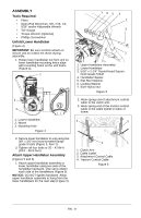
Install Discharge Chute and Discharge Chute Crank (921023, 024, 030, 032, 035) (Figures 10 and 11) 1. Grease underside of discharge chute ring (if not already greased). 2. Remove mounting hardware from auger housing (Figure 10). 3. Install discharge chute over opening in the auger housing. Finger tighten the mounting hardware removed in step 2. NOTICE: Leave discharge chute pedestal loose to help install the chute crank. . 2 921023, 024, 030, 032, 035 3 1 1 2 3 5 4 1. Mounting Holes 2. Discharge Chute 3. Chute Pedestal 4. Discharge Chute Ring 5. Mounting Hardware Figure 10 4. Insert the short end of the chute crank into the hole in the front of the control panel. NOTICE: Be careful not to damage nylon bushing when attaching crank to the control panel. 5. Connect the chute crank to the pinion gear on chute with hairpin. 1. Chute Crank 2. Control Panel 3. Hairpin Figure 11 6. Orient the chute and pedestal to its most vertical position and tighten pedestal hardware to 15 - 31 lbf-ft (20 - 42 N•m) (Figure 10). Install Discharge Chute, Chute Control and Chute Rod (921028, 029) (Figures 12, 13 and 14) 1. Grease underside of discharge chute ring (if not already greased). 2. Remove mounting hardware from auger housing. 3. Install discharge chute over opening in the auger housing. Finger tighten the mounting hardware removed in step 2. NOTICE: Leave discharge chute pedestal loose to help install the chute rod. EN - 11
-
 1
1 -
2
-
3
-
4
-
5
-
 6
6 -
 7
7 -
 8
8 -
 9
9 -
 10
10 -
 11
11 -
 12
12 -
 13
13 -
 14
14 -
 15
15 -
 16
16 -
17
-
18
-
19
-
20
-
21
-
22
-
23
-
24
-
25
-
26
-
27
-
28
-
29
-
30
-
31
-
32
-
33
-
34
-
35
-
36
-
37
-
38
-
39
-
40
-
41
-
42
 |
 |
