Adaptec AHA-1540 User Manual - Page 6
Defined, AHA-1540
 |
View all Adaptec AHA-1540 manuals
Add to My Manuals
Save this manual to your list of manuals |
Page 6 highlights
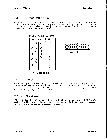
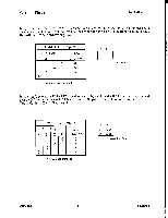
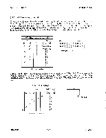
Section Three Installation 3.3.2 AT Interrupt Channel There are two jumper blocks involved in selecting the AT interrupt channel. These are J1 and J8. The AT interrupt channel jumpers consist of pin pairs 9, 10, and 11 in the large block of jumper pin pairs located in the upper right hand corner of the PCB. Pin pair 1 is the left most pair of pins. The interrupt channel reported to the AT during the Return Configuration Command is set by these jumpers according to the following table. The default is interrupt channel 11. AT Interrupt Channel Pin Pair Interrupt 9 10 11 Channel X X X Not Defined - X X Not Defined X - X 15 - - X 14 X X - 12 - X - 11 X - - 10 - - - 9 x = Jumper Installed J1 9 10 11 0 0 0 0 0 0 0 0 0 X 0 0 0 0 0 0 0 0 0 0 X 0 pin pair 1 Jumper set J8 selects the AT interrupt channel to be used by the AHA-1540. This jumper set is located just above the small AT bus connector. Pin pair 1 is the right most pair of pins. The interrupt channel used is set according to the following table. The default interrupt channel is 11. AT Interrupt Channel Pin Pair Interrupt 654 3 21 Channel 9 10 11 12 14 15 X = Jumper Installed J8 3 0 0 0 X 0 0 0 0 0 X 0 0 I-Pin Pair 1 AHA-1540 3 - 5 adaptec
-
 1
1 -
 2
2 -
 3
3 -
 4
4 -
 5
5 -
 6
6 -
 7
7 -
 8
8
 |
 |
