Acer Chromebook Spin 511 R753TN Lifecycle Extension Guide - Page 22
Mainboard Removal
 |
View all Acer Chromebook Spin 511 R753TN manuals
Add to My Manuals
Save this manual to your list of manuals |
Page 22 highlights
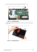
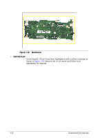
Mainboard Removal 0 Prerequisite: LCD Module Removal 1. Release the latch and disconnect the LED cable from the mainboard connector (A) (Figure 1-26). 2. Release the latch and disconnect the camera cable from the mainboard connector (B) (Figure 1-26). 3. Disconnect the microphone cable from the mainboard connector (C) (Figure 1-26). 4. Release the latch and disconnect the 20-pin USB board FFC from the mainboard connector (D) (Figure 1-26). 5. Release the latch and disconnect the 50-pin USB board FFC from the mainboard connector (E) (Figure 1-26). 6. Release the latch and disconnect the keyboard FPC from the mainboard connector (F) (Figure 1-26). 7. Release the latch and disconnect the touchpad FFC from the mainboard connector (G) (Figure 1-26). 8. Disconnect the speaker cable from the mainboard connector (H) (Figure 1-26). ! CAUTION: Make sure all cables, FFCs, and FPC are disconnected from the connectors on the mainboard to avoid damage during removal. 9. Remove seven (7) screws securing the mainboard and I/O bracket in place (Figure 1-26). B C A D E H F G Figure 1-26. Mainboard Removal 1-20 Disassembly Procedures
-
 1
1 -
2
-
3
-
4
-
5
-
6
-
7
-
8
-
9
-
10
-
11
-
12
-
13
-
14
-
15
-
16
-
 17
17 -
 18
18 -
 19
19 -
 20
20 -
 21
21 -
 22
22 -
 23
23 -
 24
24 -
 25
25 -
 26
26 -
 27
27 -
28
-
29
-
30
-
31
-
32
-
33
-
34
 |
 |
