Acer Altos R520 Acer Altos R520 User's Guide EN - Page 34
Control panel LED indicators, The following table list and describe the LED indicators available
 |
View all Acer Altos R520 manuals
Add to My Manuals
Save this manual to your list of manuals |
Page 34 highlights
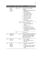
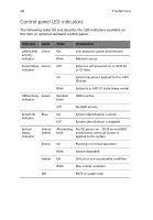
24 1 System tour Control panel LED indicators The following table list and describe the LED indicators available on the mini or optional standard control panel. Indicator Color State Description LAN1/LAN2 activity indicator Green On Blink Link between system and network Network access Power/Sleep Green Off indicator System is not powered on or ACPI S4 or S5 state On System has power applied to it or ACPI S0 state Blink System is in ACPI S1 state (sleep mode) HDD activity Green indicator Random blink HDD is active Off No HDD activity System ID Blue On indicator Off System identification is active System identification is disabled System status indicator Green/ Amber Alternating Pre DC power on - 30-35 second BMC blink initialization when AC power is applied to the system Green On Running or normal operation Blink System degraded Amber On Critical or non-recoverable condition Blink Non-critical condition Off POST or system stop
-
 1
1 -
2
-
3
-
4
-
5
-
6
-
7
-
8
-
9
-
10
-
11
-
12
-
13
-
14
-
15
-
16
-
17
-
18
-
19
-
20
-
21
-
22
-
23
-
24
-
25
-
26
-
27
-
28
-
 29
29 -
 30
30 -
 31
31 -
 32
32 -
 33
33 -
 34
34 -
 35
35 -
 36
36 -
 37
37 -
 38
38 -
 39
39 -
40
-
41
-
42
-
43
-
44
-
45
-
46
-
47
-
48
-
49
-
50
-
51
-
52
-
53
-
54
-
55
-
56
-
57
-
58
-
59
-
60
-
61
-
62
-
63
-
64
-
65
-
66
-
67
-
68
-
69
-
70
-
71
-
72
-
73
-
74
-
75
-
76
-
77
-
78
-
79
-
80
-
81
-
82
-
83
-
84
-
85
-
86
-
87
-
88
-
89
-
90
-
91
-
92
-
93
-
94
-
95
-
96
-
97
-
98
-
99
-
100
-
101
-
102
-
103
-
104
-
105
-
106
-
107
-
108
-
109
-
110
-
111
-
112
-
113
-
114
-
115
-
116
-
117
-
118
-
119
-
120
-
121
-
122
-
123
-
124
-
125
-
126
-
127
-
128
-
129
-
130
-
131
-
132
-
133
-
134
-
135
-
136
-
137
-
138
-
139
-
140
-
141
-
142
-
143
-
144
-
145
-
146
-
147
-
148
-
149
-
150
-
151
-
152
-
153
-
154
-
155
-
156
-
157
-
158
-
159
-
160
-
161
-
162
-
163
-
164
-
165
-
166
-
167
-
168
-
169
-
170
-
171
-
172
-
173
-
174
-
175
-
176
-
177
-
178
-
179
-
180
-
181
-
182
-
183
-
184
 |
 |
