2013 Yamaha Motorsports V Star 950 Owners Manual - Page 32
2013 Yamaha Motorsports V Star 950 Manual

Page 32 highlights
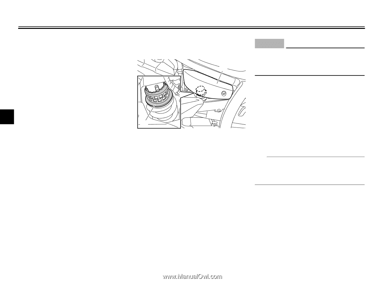
INSTRUMENT AND CONTROL FUNCTIONS To release the helmet from the helmet holder Remove the rider seat, remove the helmet from the helmet holder, and then install the seat. EAU48381 ECA10101 Adjusting the shock absorber assembly 1 NOTICE To avoid damaging the mechanism, do not attempt to turn beyond the maximum or minimum settings. Adjust the spring preload as follows. 1. Remove panel A. (See page 7-9.) 2. To increase the spring preload and thereby harden the suspension, turn the adjusting ring in direction (a). To decrease the spring preload and thereby soften the suspension, turn the adjusting ring in direction (b). TIP Align the appropriate notch in the adjusting ring with the position indicator on the shock absorber. 4 2 1. Panel A 2. Spring preload adjusting ring This shock absorber assembly is equipped with a spring preload adjusting ring, allowing the spring preload to be adjusted to suit the rider's preference. When making this adjustment, use the special wrench and extension bar included in the additional tool kit, which was handed out separately at the purchase of the vehicle. 4-13
-
 1
1 -
2
-
3
-
4
-
5
-
6
-
7
-
8
-
9
-
10
-
11
-
12
-
13
-
14
-
15
-
16
-
17
-
18
-
19
-
20
-
21
-
22
-
23
-
24
-
25
-
26
-
 27
27 -
 28
28 -
 29
29 -
 30
30 -
 31
31 -
 32
32 -
 33
33 -
 34
34 -
 35
35 -
 36
36 -
 37
37 -
38
-
39
-
40
-
41
-
42
-
43
-
44
-
45
-
46
-
47
-
48
-
49
-
50
-
51
-
52
-
53
-
54
-
55
-
56
-
57
-
58
-
59
-
60
-
61
-
62
-
63
-
64
-
65
-
66
-
67
-
68
-
69
-
70
-
71
-
72
-
73
-
74
-
75
-
76
-
77
-
78
-
79
-
80
-
81
-
82
-
83
-
84
-
85
-
86
-
87
-
88
-
89
-
90
-
91
-
92
-
93
-
94
-
95
-
96
-
97
-
98
 |
 |