2012 Yamaha Motorsports FX Nytro XTX Owners Manual - Page 36
2012 Yamaha Motorsports FX Nytro XTX Manual

Page 36 highlights
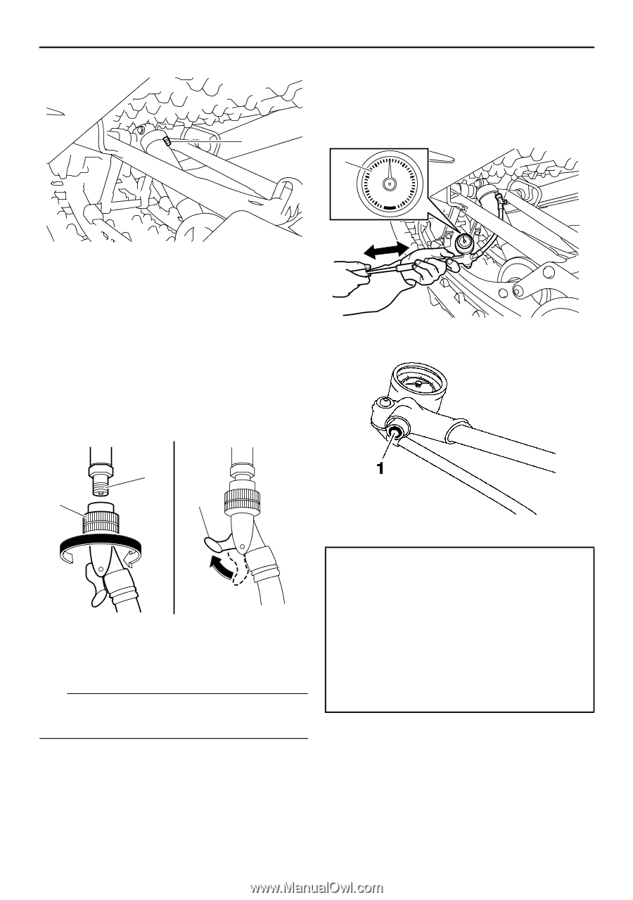
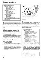
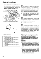
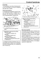
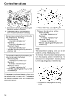
Control functions ened onto the air valve. To decrease the air pressure, push the black bleed valve button. NOTICE: Do not exceed 1406 kPa (14.1 kgf/cm², 200 psi). [ECS00981] 1 1 50 60 40 psi 70 30 80 20 100 10 0 90 1. Air valve cap 4. Install the hose connector of the shock absorber pump onto the air valve of the shock absorber, tighten it approximately six turns until the pressure registers on the pump gauge, and then pull the hose connector lock lever up. NOTICE: Do not overtighten the connector onto the air valve as this will damage the connector seal. [ECS00721] 1. Pressure gauge (low-pressure meter) 1 2 3 1. Bleed valve button 1. Air valve 2. Hose connector 3. Hose connector lock lever TIP If the shock absorber has no air pressure, the gauge reading will be zero. 5. To increase the air pressure, operate the pump a few times. The pressure should increase slowly. If the pressure increases rapidly, check to make sure that the pump is properly connected and tight- Air pressure range: FX10M53S 246-1406 kPa (2.5-14.1 kgf/cm², 36-204 psi) FX10M62S 246-1406 kPa (2.5-14.1 kgf/cm², 36-204 psi) Recommended air pressure: FX10M53S 345 kPa (3.5 kgf/cm², 50 psi) FX10M62S 345 kPa (3.5 kgf/cm², 50 psi) 30
-
 1
1 -
2
-
3
-
4
-
5
-
6
-
7
-
8
-
9
-
10
-
11
-
12
-
13
-
14
-
15
-
16
-
17
-
18
-
19
-
20
-
21
-
22
-
23
-
24
-
25
-
26
-
27
-
28
-
29
-
30
-
 31
31 -
 32
32 -
 33
33 -
 34
34 -
 35
35 -
 36
36 -
 37
37 -
 38
38 -
 39
39 -
 40
40 -
 41
41 -
42
-
43
-
44
-
45
-
46
-
47
-
48
-
49
-
50
-
51
-
52
-
53
-
54
-
55
-
56
-
57
-
58
-
59
-
60
-
61
-
62
-
63
-
64
-
65
-
66
-
67
-
68
-
69
-
70
-
71
-
72
-
73
-
74
-
75
-
76
-
77
-
78
-
79
-
80
-
81
-
82
-
83
-
84
-
85
-
86
-
87
-
88
-
89
-
90
-
91
-
92
-
93
-
94
-
95
-
96
-
97
-
98
-
99
-
100
-
101
-
102
-
103
-
104
 |
 |