2010 Yamaha Motorsports Roadliner S Owners Manual - Page 25
2010 Yamaha Motorsports Roadliner S Manual

Page 25 highlights
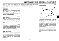
INSTRUMENT AND CONTROL FUNCTIONS Push this switch to the left to turn the optional lights on and to the right to turn them off. ECA15321 See "Multi-function meter unit" on page 4-3 for detailed information. EAU12820 Clutch lever NOTICE Do not install a bulb which exceeds 12 V, 35 W in either light, otherwise the headlight fuse may blow or the battery may discharge. EAU12711 Start switch " " Push this switch to crank the engine with the starter. See page 6-1 for starting instructions prior to starting the engine. EAU41700 4 1. Clutch lever The engine trouble warning light will come on when the key is turned to "ON" and the start switch is pushed, but this does not indicate a malfunction. EAU44602 "SELECT" switch This switch is used to perform selections in the odometer and tripmeters, to set the clock and to set the brightness control mode of the multi-function meter unit. 4-9 The clutch lever is located at the left handlebar grip. To disengage the clutch, pull the lever toward the handlebar grip. To engage the clutch, release the lever. The lever should be pulled rapidly and released slowly for smooth clutch operation. The clutch lever is equipped with a clutch switch, which is part of the ignition circuit cut-off system. (See page 4-18.)
-
 1
1 -
2
-
3
-
4
-
5
-
6
-
7
-
8
-
9
-
10
-
11
-
12
-
13
-
14
-
15
-
16
-
17
-
18
-
19
-
 20
20 -
 21
21 -
 22
22 -
 23
23 -
 24
24 -
 25
25 -
 26
26 -
 27
27 -
 28
28 -
 29
29 -
 30
30 -
31
-
32
-
33
-
34
-
35
-
36
-
37
-
38
-
39
-
40
-
41
-
42
-
43
-
44
-
45
-
46
-
47
-
48
-
49
-
50
-
51
-
52
-
53
-
54
-
55
-
56
-
57
-
58
-
59
-
60
-
61
-
62
-
63
-
64
-
65
-
66
-
67
-
68
-
69
-
70
-
71
-
72
-
73
-
74
-
75
-
76
-
77
-
78
-
79
-
80
-
81
-
82
-
83
-
84
-
85
-
86
-
87
-
88
-
89
-
90
-
91
-
92
-
93
-
94
-
95
-
96
 |
 |
