2009 Yamaha Motorsports V Star 950 Tourer Owners Manual - Page 33
2009 Yamaha Motorsports V Star 950 Tourer Manual

Page 33 highlights
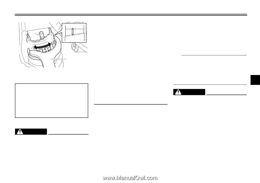
INSTRUMENT AND CONTROL FUNCTIONS ● 2 (b) 1 2 34 5 67 8 9 (a) 1 1. Special wrench 2. Position indicator ● ● Spring preload setting: Minimum (soft): 1 Standard: 4 Maximum (hard): 9 open the cylinder assembly. Do not subject the shock absorber assembly to an open flame or other high heat source. This may cause the unit to explode due to excessive gas pressure. Do not deform or damage the cylinder in any way. Cylinder damage will result in poor damping performance. Do not dispose of a damaged or worn-out shock absorber assembly yourself. Take the shock absorber assembly to a Yamaha dealer for any service. EAU15301 Sidestand The sidestand is located on the left side of the frame. Raise the sidestand or lower it with your foot while holding the vehicle upright. TIP The built-in sidestand switch is part of the ignition circuit cut-off system, which cuts the ignition in certain situations. (See further down for an explanation of the ignition circuit cut-off system.) EWA10240 2 3 4 5 6 7 8 9 3. Install the panel. EWA10221 WARNING This shock absorber assembly contains highly pressurized nitrogen gas. Read and understand the following information before handling the shock absorber assembly. ● Do not tamper with or attempt to 4-15 WARNING The vehicle must not be ridden with the sidestand down, or if the sidestand cannot be properly moved up (or does not stay up), otherwise the sidestand could contact the ground and distract the operator, resulting in a possible loss of control. Yamaha's ignition circuit cut-off system has been designed to assist the operator in fulfilling the responsibility of raising the sidestand before starting off. Therefore, check this system regularly as described below and have a Yamaha dealer re-
-
 1
1 -
2
-
3
-
4
-
5
-
6
-
7
-
8
-
9
-
10
-
11
-
12
-
13
-
14
-
15
-
16
-
17
-
18
-
19
-
20
-
21
-
22
-
23
-
24
-
25
-
26
-
27
-
 28
28 -
 29
29 -
 30
30 -
 31
31 -
 32
32 -
 33
33 -
 34
34 -
 35
35 -
 36
36 -
 37
37 -
 38
38 -
39
-
40
-
41
-
42
-
43
-
44
-
45
-
46
-
47
-
48
-
49
-
50
-
51
-
52
-
53
-
54
-
55
-
56
-
57
-
58
-
59
-
60
-
61
-
62
-
63
-
64
-
65
-
66
-
67
-
68
-
69
-
70
-
71
-
72
-
73
-
74
-
75
-
76
-
77
-
78
-
79
-
80
-
81
-
82
-
83
-
84
-
85
-
86
-
87
-
88
-
89
-
90
-
91
-
92
-
93
-
94
-
95
-
96
-
97
-
98
-
99
-
100
 |
 |