2008 Yamaha Motorsports RS Vector GT Owners Manual - Page 47
2008 Yamaha Motorsports RS Vector GT Manual

Page 47 highlights
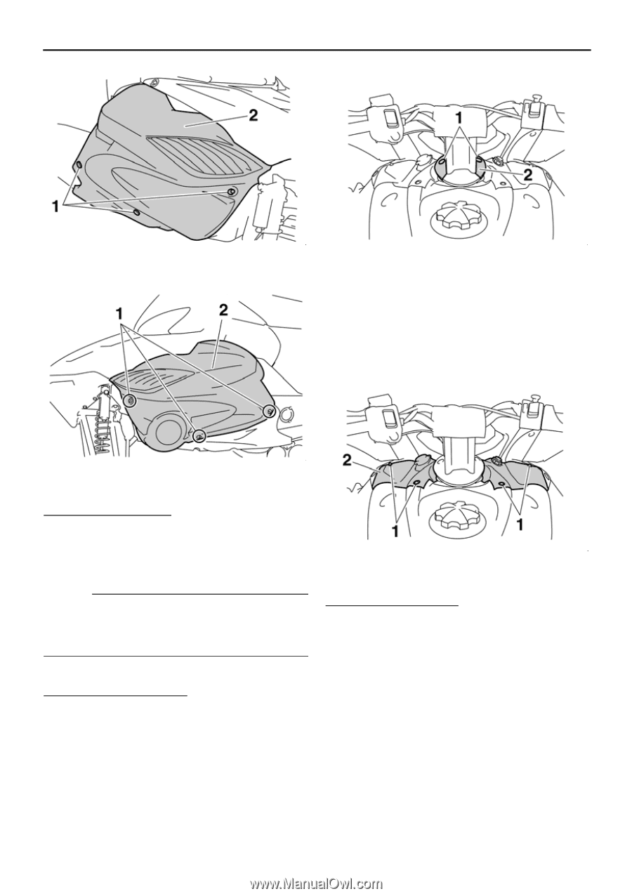
Periodic maintenance 1. Fastener 2. Right side cover 1. Screw 2. Cable guide 3. Loosen the quick fastener screws, disconnect the main switch coupler and auxiliary DC jack coupler (RS90GT / RS90GTA / RS90LTGT), and then remove the top cover. 1. Fastener 2. Left side cover To install a side cover 1. Place the side cover in the original position, and then tighten the fasteners. 2. Install the shroud. 1. Quick fastener screw 2. Top cover NOTE: Be sure to fit the projection on the rear of the side cover into the hole in the lower side cover. Top cover To remove the top cover 1. Remove the shroud. (See the above procedure.) 2. Remove the screws, and then remove the cable guide. To install the top cover 1. Connect the main switch coupler and auxiliary DC jack coupler (RS90GT / RS90GTA / RS90LTGT), place the top cover in the original position, and then tighten the quick fastener screws. 2. Pass all of the cables, etc., through the cable guide, place the cable guide in the original position, and then install the screws. 3. Install the shroud. 41
-
 1
1 -
2
-
3
-
4
-
5
-
6
-
7
-
8
-
9
-
10
-
11
-
12
-
13
-
14
-
15
-
16
-
17
-
18
-
19
-
20
-
21
-
22
-
23
-
24
-
25
-
26
-
27
-
28
-
29
-
30
-
31
-
32
-
33
-
34
-
35
-
36
-
37
-
38
-
39
-
40
-
41
-
 42
42 -
 43
43 -
 44
44 -
 45
45 -
 46
46 -
 47
47 -
 48
48 -
 49
49 -
 50
50 -
 51
51 -
 52
52 -
53
-
54
-
55
-
56
-
57
-
58
-
59
-
60
-
61
-
62
-
63
-
64
-
65
-
66
-
67
-
68
-
69
-
70
-
71
-
72
-
73
-
74
-
75
-
76
-
77
-
78
-
79
-
80
-
81
-
82
-
83
-
84
-
85
-
86
-
87
-
88
-
89
-
90
 |
 |