ViewSonic LD-STND-003 Quick Start Guide - Page 6
Connec°ng the System Control Box to the Floor Base
 |
View all ViewSonic LD-STND-003 manuals
Add to My Manuals
Save this manual to your list of manuals |
Page 6 highlights
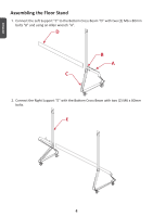
ENGLISH Connecting the System Control Box to the Floor Base 1. Carefully unfold the System Control Box panel. Ensure the main system control board is on the left. NOTE: Use caution as the System Control Box panel is separated into two pieces with wires attached. 2. Align the System Control Box to the six (6) holes on the Bottom Cross Beam and secure it with six (6) M6x10mm screws. 3. Install two (2) additional screws (M6x10mm) to connect the two halves of the System Control Box. NOTE: Screws (M6x10mm) are placed in the accessory box of the LED Display. 6
-
 1
1 -
 2
2 -
 3
3 -
 4
4 -
 5
5 -
 6
6 -
 7
7 -
 8
8 -
 9
9 -
 10
10 -
 11
11 -
 12
12 -
13
-
14
-
15
-
16
-
17
-
18
-
19
-
20
-
21
-
22
-
23
-
24
-
25
-
26
-
27
-
28
-
29
-
30
-
31
-
32
-
33
-
34
-
35
-
36
-
37
-
38
-
39
-
40
-
41
-
42
-
43
-
44
-
45
-
46
-
47
-
48
-
49
-
50
-
51
-
52
-
53
-
54
-
55
-
56
-
57
-
58
-
59
-
60
-
61
-
62
-
63
-
64
-
65
-
66
-
67
-
68
-
69
-
70
-
71
-
72
-
73
-
74
-
75
-
76
-
77
-
78
-
79
-
80
-
81
-
82
-
83
-
84
-
85
-
86
-
87
-
88
-
89
-
90
-
91
-
92
-
93
-
94
-
95
-
96
-
97
-
98
-
99
-
100
-
101
-
102
-
103
-
104
-
105
-
106
-
107
-
108
-
109
-
110
-
111
-
112
-
113
-
114
-
115
-
116
-
117
-
118
-
119
-
120
-
121
-
122
 |
 |

ENGLISH
6
Connec°ng the System Control Box to the Floor Base
². Carefully unfold the System Control Box panel. Ensure the main system control board
is on the left.
NOTE:
Use cau°on as the System Control Box panel is separated into two pieces with
wires a±ached.
³. Align the System Control Box to the six (´) holes on the Bottom Cross Beam and se-
cure it with six (´) M´x²¶mm screws.
3. Install two (³) additional screws (M´x²¶mm) to connect the two halves of the System
Control Box.
NOTE:
Screws (M6x10mm) are placed in the accessory box of the LED Display.