URC MRX-10 Owners Manual - Page 6
Rear Panel Descriptions - advanced network system controller
 |
View all URC MRX-10 manuals
Add to My Manuals
Save this manual to your list of manuals |
Page 6 highlights
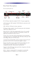
MRX-10 ADVANCED NETWORK SYSTEM CONTROLLER Rear Panel Descriptions The rear panel ports are: LAN IR Outputs: #1-8 Sensors RS-232 Ports RFTX-1 DC 12V URC Power USB Relay: NO, NC, COM 12V Out Trigger In DC 12V Power: Attach the included 12V DC 3.5A power supply here. LAN Connection: RJ45 standard 10/100 Ethernet connection to the local network. URC USB Port: USB port for future expansion. IR Outputs: Eight standard 3.5mm IR emitter ports with individual output level adjustment screws. Relays NO, NC, COM: Two programmable relays to be normally opened (NO), normally closed (NC) or momentary contacts. An application should be less than 30V/.5A. Sensors: Four sensor ports allow programming of state dependent and triggered macros. Compatible with URC Video (URC part: VID) and voltage (URC part: VS-100) sensors. 12V OUT: Two programmable 12V/0.2A outputs. Each may be programmed to turn on, off or momentarily toggle its output. RS-232: Four RS-232 ports support Tx(Transmit), Rx(Receive) and GND(Ground) connections for two way communication. Compatible with URC cables RS232F and RS232M. Trigger In: IR and RF trigger input ports allow integration with other control systems and remotes. RFTX-1: Attach an optional RFTX-1 transmitter to control URC Lighting products via 418MHz or 433.92MHz wireless RF. Page 3
-
 1
1 -
 2
2 -
 3
3 -
 4
4 -
 5
5 -
 6
6 -
 7
7 -
 8
8 -
 9
9 -
 10
10 -
 11
11 -
 12
12 -
13
-
14
-
15
-
16
 |
 |
