URC DMS-100 Owners Manual - Page 17
System Configuration for Internal LAN Network
 |
View all URC DMS-100 manuals
Add to My Manuals
Save this manual to your list of manuals |
Page 17 highlights
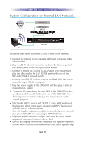
DMS-100 SYSTEM CONFIGURATION System Configuration for Internal LAN Network Internet Cable Modem WiFi Router MFS-8 DMS-100 PC Follow the steps below to connect a DMS-100 to a LAN network. 1. Connect the Internet to the coaxial CABLE port in the rear of the cable modem. 2. Plug in a RJ-45 ethernet connector cable via the Ethernet port of the cable modem to the WAN port of the Router. 3. Connect a second RJ-45 cable to a LAN port of the Router and plug the other end to the LAN 10/100 port on the rear of the MFS-8/MFSPOE-8 network Switch. 4. Connect a third RJ-45 cable to connect the DMS-100 LAN port to one of the eight 10/100 Smart ports. 5. Plug the power supply to the DMS-100 and then plug it in to an unswitched AC outlet. 6. Connect a PC computer to the same LAN as the DMS-100 or plug an ethernet cable directly to the LAN port of the DMS-100. Now the computer can control and adjust the manufacturer's audio control program. Select audio INPUT source and OUTPUT zone, MAC address etc. This function selects input source channel and INPUT gain level and data sent to audio equipment. After selecting the output zone, adjust the zone limit power rate and zone power ON/OFF and source signal INPUT channel. Adjust the amplifier volume level per each zone for proper sound output and maximum limitation volume level. Turn on the ramp up volume level and adjust the equalizer repertory and low volume loudness control effectiveness and custom equalizer align. Page 15
-
 1
1 -
2
-
3
-
4
-
5
-
6
-
7
-
8
-
9
-
10
-
11
-
 12
12 -
 13
13 -
 14
14 -
 15
15 -
 16
16 -
 17
17 -
 18
18 -
 19
19
 |
 |
