Toshiba TLP680U Owners Manual - Page 12
Left side, Right side, Rear side, RGB INPUT connectors RGB input, AUDIO input
 |
UPC - 022265950876
View all Toshiba TLP680U manuals
Add to My Manuals
Save this manual to your list of manuals |
Page 12 highlights
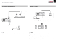
Before use (Continued) Left side Right side CONTENTS 12 1 2 34 RS-232C CONTROL RGB AUDIO MONITOR OUTPUT RGB AUDIO RGB INPUT AC IN socket 19 Rear side Carrying handle Open to carry the projetor. Speaker Infrared remote sensor Intake holes VIDEO INPUT S-VIDEO VIDEO L - AUDIO -R Anti-theft lock 1 CONTROL connector 17 49 To connect a computer to control the projector. 2 MONITOR OUTPUT connectors (RGB output, AUDIO output) 17 To connect to a monitor or audio equipment. 3 RGB INPUT connectors (RGB input, AUDIO input) 16 To connect a computer, etc. 4 VIDEO INPUT connectors (S-VIDEO input, VIDEO input, AUDIO input) 17 To connect a video equipment, etc. Document imaging camera model (Continued)
-
 1
1 -
2
-
3
-
4
-
5
-
6
-
 7
7 -
 8
8 -
 9
9 -
 10
10 -
 11
11 -
 12
12 -
 13
13 -
 14
14 -
 15
15 -
 16
16 -
 17
17 -
18
-
19
-
20
-
21
-
22
-
23
-
24
-
25
-
26
-
27
-
28
-
29
-
30
-
31
-
32
-
33
-
34
-
35
-
36
-
37
-
38
-
39
-
40
-
41
-
42
-
43
-
44
-
45
-
46
-
47
-
48
-
49
-
50
-
51
-
52
-
53
-
54
 |
 |

CONTENTS
12
Before use
(Continued)
Left side
Right side
AC IN socket
19
Carrying handle
Open to carry the projetor.
Rear side
CONTROL connector
17
49
To connect a computer to control the projector.
MONITOR OUTPUT connectors
(RGB output, AUDIO output)
17
To connect to a monitor or audio equipment.
RGB INPUT connectors (RGB input, AUDIO input)
16
To connect a computer, etc.
VIDEO INPUT connectors
(S-VIDEO input, VIDEO input, AUDIO input)
17
To connect a video equipment, etc.
(Continued)
Document imaging camera model
1
2
3
4
RS-232C
CONTROL
RGB
AUDIO
MONITOR OUTPUT
RGB
S-VIDEO
VIDEO
VIDEO INPUT
L - AUDIO -R
AUDIO
RGB INPUT
1
2
3
4
Speaker
Infrared remote sensor
Intake holes
Anti-theft lock