TRENDnet TV-IP340PI Users Guide - Page 10
Mounting
 |
View all TRENDnet TV-IP340PI manuals
Add to My Manuals
Save this manual to your list of manuals |
Page 10 highlights
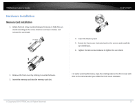
TRENDnet User's Guide Mounting 1. Attach the drill template (supplied) to the wall or the ceiling where the camera is to be mounted. 2. Drill screw holes in the wall or ceiling according to the Hole 1 on the drill template. Drill Template TV-IP340PI Drill Template 2 Ceiling Mounting 1 1 2 1:Screw Hole for Bracket 1 2 2 2:Screw Hole for Mounting Base 1 6. Adjust the view angle. 3‐axis (pan/tilt/rotation) adjusting allows adjustment for optimum camera rotation and placement. Follow the steps below to adjust the view angle. Pan Adjustment 1). Loosen the lock screw 1. 2). Adjust the panning position of the camera. The adjusting range is from 0° to 360°. 3). Tighten the lock screw 1. 3. If you need to route cables through the wall (or the ceiling), cut a cable hole according to the drill template. Skip this step, if you want to route the cables on the surface of the wall (or the ceiling). 4. Route the cables of the camera. 5. Secure the camera to the wall (or the ceiling) with expansion screws. Tilt Adjustment 1). Loosen the lock screw 2. 2). Adjust the tilting position of the camera. The adjusting range is from 0° to 100°. 3). Tighten the lock screw 2. © Copyright 2016 TRENDnet. All Rights Reserved. 10
-
 1
1 -
2
-
3
-
4
-
 5
5 -
 6
6 -
 7
7 -
 8
8 -
 9
9 -
 10
10 -
 11
11 -
 12
12 -
 13
13 -
 14
14 -
 15
15 -
16
-
17
-
18
-
19
-
20
-
21
-
22
-
23
-
24
-
25
-
26
-
27
-
28
-
29
-
30
-
31
-
32
-
33
-
34
-
35
-
36
-
37
-
38
-
39
-
40
-
41
-
42
-
43
-
44
-
45
-
46
-
47
-
48
-
49
-
50
-
51
-
52
-
53
-
54
-
55
-
56
-
57
-
58
-
59
 |
 |
