Stihl SH 85 Instruction Manual - Page 26
Main Parts
 |
View all Stihl SH 85 manuals
Add to My Manuals
Save this manual to your list of manuals |
Page 26 highlights
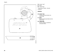
English Main Parts 13 14 15 2* 1 3 4 67 9 5 8 10 11 12 19 1 Tab 2 Setting Lever* 3 Spark Plug Boot 4 Muffler 5 Starter Grip 6 Carburetor Adjusting Screw 7 Choke Lever 8 Manual Fuel Pump 9 Filter Housing 10 Fuel Filler Cap 11 Fuel Tank 12 Assist Handle 13 Control Handle 14 Switch 15 Throttle Trigger 16 Intake Screen 17 Blower Tube 18 Round Nozzle 19 Fan Nozzle* # Serial Number * Depending on Model - Special Accessory 17 16 Definitions 18 1. Tab Designed to secure the blower tube to the machine. # 2. Setting Lever Holds the throttle trigger in position. 295BA081 KN 3. Spark Plug Boot Connects the spark plug to the ignition lead. 24 BG 55, BG 65, BG 85, SH 55, SH 85
-
 1
1 -
2
-
3
-
4
-
5
-
6
-
7
-
8
-
9
-
10
-
11
-
12
-
13
-
14
-
15
-
16
-
17
-
18
-
19
-
20
-
 21
21 -
 22
22 -
 23
23 -
 24
24 -
 25
25 -
 26
26 -
 27
27 -
 28
28 -
 29
29 -
 30
30 -
 31
31 -
32
-
33
-
34
-
35
-
36
-
37
-
38
-
39
-
40
-
41
-
42
-
43
-
44
-
45
-
46
-
47
-
48
-
49
-
50
-
51
-
52
-
53
-
54
-
55
-
56
-
57
-
58
-
59
-
60
-
61
-
62
-
63
-
64
-
65
-
66
-
67
-
68
-
69
-
70
-
71
-
72
-
73
-
74
-
75
-
76
 |
 |

BG 55, BG 65, BG 85, SH 55, SH 85
English
24
1
Tab
2
Setting Lever
*
3
Spark Plug Boot
4
Muffler
5
Starter Grip
6
Carburetor Adjusting Screw
7
Choke Lever
8
Manual Fuel Pump
9
Filter Housing
10
Fuel Filler Cap
11
Fuel Tank
12
Assist Handle
13
Control Handle
14
Switch
15
Throttle Trigger
16
Intake Screen
17
Blower Tube
18
Round Nozzle
19
Fan Nozzle
*
#
Serial Number
* Depending on Model – Special
Accessory
Definitions
1.
Tab
Designed to secure the blower tube
to the machine.
2.
Setting Lever
Holds the throttle trigger in position.
3.
Spark Plug Boot
Connects the spark plug to the
ignition lead.
Main Parts
11
12
1
13
14
#
16
6
15
10
9
8
5
2*
7
4
3
17
18
295BA081 KN
19